
Page 99 - Marks Calculation for Machine Design
P. 99
P1: Sanjay
January 4, 2005
Brown˙C02
Brown.cls
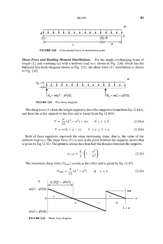
A 16:18 BEAMS w 81
C
B
L a
FIGURE 2.60 Concentrated force at intermediate point.
Shear Force and Bending Moment Distributions. For the single overhanging beam of
length (L) and overhang (a) with a uniform load (w), shown in Fig. 2.60, which has the
balanced free-body-diagram shown in Fig. 2.61, the shear force (V ) distribution is shown
in Fig. 2.62.
w
A = 0
x
2
2
2
A = w(L – a )/2L B = w(L + a) /2L
y
y
FIGURE 2.61 Free-body-diagram.
Theshearforce(V )fromtheleftpinsupporttotherollersupportisfoundfromEq.(2.41a),
and from the roller support to the free end is found from Eq. (2.41b).
w 2 2
V = (L − a ) − wx 0 ≤ x ≤ L (2.41a)
2L
V = w(L + a − x) L ≤ x ≤ L + a (2.41b)
Both of these equations represent the same decreasing slope, that is, the value of the
uniform load (w). The shear force (V ) is zero at the point between the supports shown that
is given by Eq. (2.42). This point is always less than half the distance between the supports.
L a 2
x V =0 = 1 − 2 (2.42)
2 L
The maximum shear force (V max ) occurs at the roller and is given by Eq. (2.43).
w 2 2
V max = (L + a ) at x = L (2.43)
2L
V (L /2)[1 – a /L ]
2
2
2
2
w(L – a )/2L wa
+ +
0 x
L – a
L + a
2
2
w(L + a )/2L
FIGURE 2.62 Shear force diagram.