Page 96 - Marks Calculation for Machine Design
P. 96

P1: Sanjay
                          January 4, 2005
                 Brown˙C02
        Brown.cls
                  78
                            U.S. Customary 16:18  STRENGTH OF MACHINES  SI/Metric
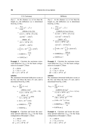
                  Step 2. As the distance (x) is less than the  Step 2. As the distance (x) is less than the
                  length (L), the deflection ( ) is determined  length (L), the deflection ( ) is determined
                  from Eq. (2.38a).                  from Eq. (2.38a).
                           Fax  2   2                       Fax  2   2
                         =    (L − x ) ↑                  =     (L − x ) ↑
                           6 EIL                            6 EIL
                             (450 lb)(1ft)(2ft)              (2,000 N)(0.3m)(0.6m)
                         =                                =
                                                                     6
                                       2
                                                                         2
                                  6
                           6 (2.5 × 10 lb · ft )(3ft)       6 (1.02 × 10 N · m )(1m)
                                                                         2
                               2
                                     2
                                                                 2
                          ×[(3ft) − (2ft) ]                 × [(1m) − (0.6m) ]
                                                                     2
                                    2
                             (900 lb · ft )                    (360 N · m )
                         =                                =        6    3
                                      3
                                 7
                           (4.5 × 10 lb · ft )              (6.12 × 10 N · m )
                                                                         2
                                                                2
                                     2
                               2
                          ×[(9ft ) − (4ft )]                ×[(1m ) − (0.36 m )]

                                   1                               −5  1       2
                                          2
                         =  2.0 × 10 −5  × [5 ft ]        =  5.88 × 10  × [0.64 m ]
                                   ft                                m
                                  12 in                              100 cm
                         = 0.0001 ft ×                    = 0.000038 m ×  m
                                   ft
                         = 0.0012 in ↑                    = 0.0038 cm ↑
                  Example 5. Calculate the maximum down-  Example 5. Calculate the maximum down-
                  ward deflection (  max ) for the beam configu-  ward deflection (  max ) for the beam configu-
                  ration in Example 4, where         ration in Example 4, where
                    F = 450 lb                         F = 2,000 N
                    L = 3 ft, a = 1ft                  L = 1m, a = 0.3 m
                             6
                                                                 6
                    EI = 2.5 × 10 lb · ft 2            EI = 1.02 × 10 N · m 2
                  solution                           solution
                  The maximum downward deflection occurs at  The maximum downward deflection occurs at
                  the free end where the force (F) acts, and is  the free end where the force (F) acts, and is
                  determined from Eq. (2.40).        determined from Eq. (2.40).
                          Fa 2                              Fa 2
                      max =  (L + a)                   max =   (L + a)
                          3 EI                             3 EI
                            (450 lb)(1ft) 2                 (2,000 N)(0.3m) 2
                        =             2  (3ft + 1ft)     =          6   2  (1m + 0.3m)
                                 6
                          3 (2.5 × 10 lb · ft )            3 (1.02 × 10 N · m )
                            450 lb · ft 2                     180 N · m 2
                        =            (4ft)               =        6   2  (1.3m)
                                6
                          7.5 × 10 lb · ft 2               3.06 × 10 N · m
                        = (6.0 × 10 −5 )(4ft)            = (5.88 × 10 −5 )(1.3m)
                                   12 in                             100 cm
                        = 0.00024 ft ×                   = 0.000076 m ×  m
                                    ft
                        = 0.0029 in ↓                    = 0.0076 cm ↓
                  Example 6. Calculate and locate the maxi-  Example 6. Calculate and locate the maxi-
                  mum upward deflection (  max ) for the beam  mum upward deflection (  max ) for the beam
                  configuration of Example 4, where   configuration of Example 4, where
                     F = 450 lb                        F = 2,000 N
                     L = 3 ft, a = 1ft                 L = 1m, a = 0.3 m
                              6
                                                                 6
                    EI = 2.5 × 10 lb · ft 2            EI = 1.02 × 10 N · m 2
   91   92   93   94   95   96   97   98   99   100   101