
Page 92 - Marks Calculation for Machine Design
P. 92
P1: Sanjay
January 4, 2005
Brown˙C02
Brown.cls
74
U.S. Customary 16:18 STRENGTH OF MACHINES SI/Metric
Step 2. From Fig. 2.52 calculate the roller Step 2. From Fig. 2.52 calculate the roller
reaction (B y ) as reaction (B y ) as
F(L + a) (450 lb)(3ft + 1ft) F(L + a) (2,000 N)(1m + 0.3m)
B y = = B y = =
L 3ft L 1m
1,800 ft · lb 2,600 N · m
= = 600 lb = = 2,600 N
3ft 1m
F
A
C
B
L a
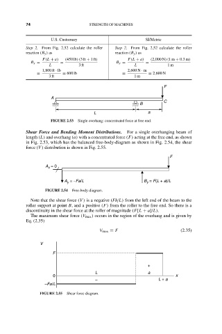
FIGURE 2.53 Single overhang: concentrated force at free end.
Shear Force and Bending Moment Distributions. For a single overhanging beam of
length (L) and overhang (a) with a concentrated force (F) acting at the free end, as shown
in Fig. 2.53, which has the balanced free-body-diagram as shown in Fig. 2.54, the shear
force (V ) distribution is shown in Fig. 2.55.
F
A = 0
x
A = −Fa/L B = F(L + a)/L
y
y
FIGURE 2.54 Free-body-diagram.
Note that the shear force (V ) is a negative (Fb/L) from the left end of the beam to the
roller support at point B, and a positive (F) from the roller to the free end. So there is a
discontinuity in the shear force at the roller of magnitude (F[L + a]/L).
The maximum shear force (V max ) occurs in the region of the overhang and is given by
Eq. (2.35)
V max = F (2.35)
V
F
+
L a
0 x
– L + a
–Fa/L
FIGURE 2.55 Shear force diagram.