
Page 94 - Marks Calculation for Machine Design
P. 94
P1: Sanjay
January 4, 2005
Brown˙C02
Brown.cls
76
U.S. Customary 16:18 STRENGTH OF MACHINES SI/Metric
Step 2. As the distance (x) is less than the Step 2. As the distance (x) is less than the
length (L), the bending moment (M) is deter- length (L), the bending moment (M) is deter-
mined from Eq. (2.36a). mined from Eq. (2.36a).
Fa (450 1b)(1ft) Fa (2,000 N)(0.3m)
M =− x =− (2ft) M =− x =− (0.6m)
L 3ft L 1m
450 ft · lb 600 N · m
=− (2ft) =− (0.6m)
3ft 1m
=−(150 lb)(2ft) =−300 ft · lb =−(600 N)(0.6m) =−360 N · m
Example 3. Calculate and locate the max- Example 3. Calculate and locate the max-
imum shear force (V max ) and the maximum imum shear force (V max ) and the maximum
bending moment (M max ) for the beam of bending moment (M max ) for the beam of
Example 2, where Example 2, where
F = 450 lb F = 2,000 N
L = 3 ft, a = 1ft L = 1m, a = 0.3 m
solution solution
Step 1. Calculate the maximum shear force Step 1. Calculate the maximum shear force
(V max ) from Eq. (2.35) as (V max ) from Eq. (2.35) as
V max = F = 450 lb V max = F = 2,000 N
Step 2. From Fig. 2.55 this maximum shear Step 2. Figure 2.55 shows that this maximum
force (V max ) of 450 lb occurs in the region of shear force (V max ) of 2,000 N occurs in the re-
the overhang. gion of the overhang.
Step 3. Calculate the maximum bending mo- Step 3. Calculate the maximum bending mo-
ment (M max ) from Eq. (2.37) as ment (M max ) from Eq. (2.37) as
M max = Fa = (450 lb)(1ft) M max = Fa = (2,000 N)(0.3m)
= 450 ft · lb = 600 N · m
Step 4. Figure 2.56 shows that this maximum Step 4. Figure 2.56 shows that this maximum
bending moment (M max ) of 450 ft · lb occurs at bending moment (M max ) of 600 N · m occurs at
the roller. the roller.
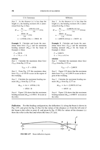
Deflection. For this loading configuration, the deflection ( ) along the beam is shown in
Fig. 2.57, and given by Eq. (2.38a) for the values of the distance (x) from the left end of
the beam to the roller at point B, and given by Eq. (2.38b) for values of the distance (x)
from the roller to the free end where the force (F) acts.
F
B
A
∆ C
L a
FIGURE 2.57 Beam deflection diagram.