
Page 89 - Marks Calculation for Machine Design
P. 89
P1: Sanjay
January 4, 2005
Brown˙C02
Brown.cls
a 16:18 F BEAMS F a 71
A B
∆
L
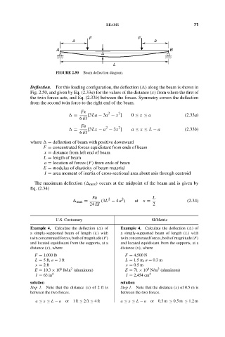
FIGURE 2.50 Beam deflection diagram.
Deflection. For this loading configuration, the deflection ( ) along the beam is shown in
Fig. 2.50, and given by Eq. (2.33a) for the values of the distance (x) from where the first of
the twin forces acts, and Eq. (2.33b) between the forces. Symmetry covers the deflection
from the second twin force to the right end of the beam.
Fx 2 2
= [3La − 3a − x ] 0 ≤ x ≤ a (2.33a)
6 EI
Fa 2 2
= [3Lx − a − 3x ] a ≤ x ≤ L − a (2.33b)
6 EI
where = deflection of beam with positive downward
F = concentrated forces equidistant from ends of beam
x = distance from left end of beam
L = length of beam
a = location of forces (F) from ends of beam
E = modulus of elasticity of beam material
I = area moment of inertia of cross-sectional area about axis through centroid
The maximum deflection ( max ) occurs at the midpoint of the beam and is given by
Eq. (2.34)
Fa 2 2 L
max = (3L − 4 a ) at x = (2.34)
24 EI 2
U.S. Customary SI/Metric
Example 4. Calculate the deflection ( ) of Example 4. Calculate the deflection ( ) of
a simply-supported beam of length (L) with a simply-supported beam of length (L) with
twinconcentratedforces,bothofmagnitude(F) twinconcentratedforces,bothofmagnitude(F)
and located equidistant from the supports, at a and located equidistant from the supports, at a
distance (x), where distance (x), where
F = 1,000 lb F = 4,500 N
L = 5 ft, a = 1ft L = 1.5 m, a = 0.3 m
x = 2ft x = 0.5 m
9
6
2
2
E = 10.3 × 10 lb/in (aluminum) E = 71 × 10 N/m (aluminum)
I = 63 in 4 I = 2,454 cm 4
solution solution
Step 1. Note that the distance (x) of2ftis Step 1. Note that the distance (x) of 0.5 m is
between the two forces. between the two forces.
a ≤ x ≤ L − a or 1 ft ≤ 2ft ≤ 4ft a ≤ x ≤ L − a or 0.3m ≤ 0.5m ≤ 1.2m