
Page 86 - Marks Calculation for Machine Design
P. 86
P1: Sanjay
January 4, 2005
Brown˙C02
Brown.cls
68
U.S. Customary 16:18 STRENGTH OF MACHINES SI/Metric
Example 1. Determine the reactions at the Example 1. Determine the reactions at the
ends of a simply-supported beam of length (L) ends of a simply-supported beam of length (L)
with twin concentrated forces, both of magni- with twin concentrated forces, both of magni-
tude (F) and located equidistant from the sup- tude (F) and located equidistant from the sup-
ports, where ports, where
F = 1,000 lb F = 4,500 N
L = 5 ft, a = 1ft L = 1.5 m, a = 0.3 m
solution solution
Step 1. From Fig. 2.45 calculate the pin reac- Step 1. From Fig. 2.45 calculate the pin reac-
tions (A x and A y ) at the left end of the beam. tions (A x and A y ) at the left end of the beam.
As the forces are acting directly downward, As the forces are acting directly downward,
A x = 0 A x = 0
and the vertical reaction (A y ) is and the vertical reaction (A y ) is
A y = F = 1,000 lb A y = F = 4,500 N
Step 2. From Fig. 2.45 calculate the roller Step 2. From Fig. 2.45 calculate the roller
reaction (B y ) at the right end of the beam. reaction (B y ) at the right end of the beam.
B y = F = 1,000 lb B y = F = 4,500 N
F F
a a
A B
L
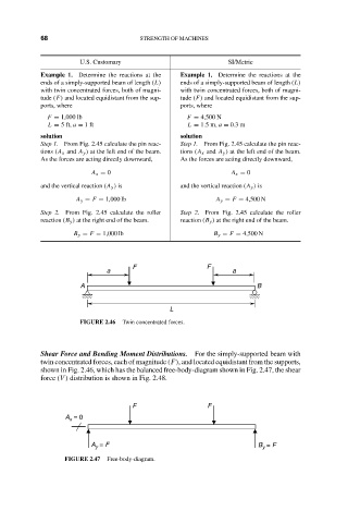
FIGURE 2.46 Twin concentrated forces.
Shear Force and Bending Moment Distributions. For the simply-supported beam with
twin concentrated forces, each of magnitude (F), and located equidistant from the supports,
shown in Fig. 2.46, which has the balanced free-body-diagram shown in Fig. 2.47, the shear
force (V ) distribution is shown in Fig. 2.48.
F F
A = 0
x
A = F B = F
y
y
FIGURE 2.47 Free-body-diagram.