
Page 81 - Marks Calculation for Machine Design
P. 81
P1: Sanjay
16:18
January 4, 2005
Brown.cls
Brown˙C02
BEAMS
The shear force (V ) is given by Eq. (2.24)
2
63
wL x
V = 1 − 3 (2.24)
6 L
The maximum shear force (V max ) is therefore given by Eq. (2.25)
wL
V max = at x = L (2.25)
3
The bending moment distribution is given by Eq. (2.26) for the values of the distance (x)
from the left end of the beam.
2
wLx x L
M = 1 − at x = √ = 0.577 L (2.26)
6 L 3
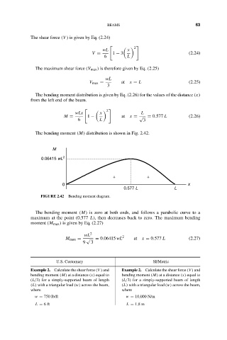
The bending moment (M) distribution is shown in Fig. 2.42.
M
0.06415 wL 2
+ +
0 x
0.577 L L
FIGURE 2.42 Bending moment diagram.
The bending moment (M) is zero at both ends, and follows a parabolic curve to a
maximum at the point (0.577 L), then decreases back to zero. The maximum bending
moment (M max ) is given by Eq. (2.27)
wL 2 2
M max = √ = 0.06415 wL at x = 0.577 L (2.27)
9 3
U.S. Customary SI/Metric
Example 2. Calculate the shear force (V ) and Example 2. Calculate the shear force (V ) and
bending moment (M) at a distance (x) equal to bending moment (M) at a distance (x) equal to
(L/3) for a simply-supported beam of length (L/3) for a simply-supported beam of length
(L) with a triangular load (w) across the beam, (L) with a triangular load (w) across the beam,
where where
w = 750 lb/ft w = 10,000 N/m
L = 6ft L = 1.8 m