Page 77 - Marks Calculation for Machine Design
P. 77

P1: Sanjay
                          January 4, 2005
                 Brown˙C02
        Brown.cls
                              A       16:18      BEAMS                   w         59
                                                                          B
                                               D
                                                    L
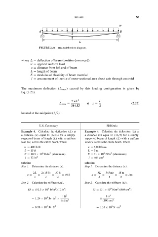
                              FIGURE 2.36  Beam deflection diagram.
                    where   = deflection of beam (positive downward)
                         w = applied uniform load
                         x = distance from left end of beam
                         L = length of beam
                         E = modulus of elasticity of beam material
                         I = area moment of inertia of cross-sectional area about axis through centroid

                    The maximum deflection (  max ) caused by this loading configuration is given by
                    Eq. (2.23),

                                               5 wL 4         L
                                           max =        at  x =                 (2.23)
                                               384 EI          2
                    located at the midpoint (L/2).


                              U.S. Customary                      SI/Metric
                    Example 4. Calculate the deflection ( ) at  Example 4. Calculate the deflection ( ) at
                    a distance (x) equal to (2L/3) for a simply-  a distance (x) equal to (3L/5) for a simply-
                    supported beam of length (L) with a uniform  supported beam of length (L) with a uniform
                    load (w) across the entire beam, where  load (w) across the entire beam, where
                     w = 400 lb/ft                      w = 6,000 N/m
                      L = 15 ft                         L = 5m
                                   2
                               6
                                                                 9
                                                                     2
                      E = 10.3 × 10 lb/in (aluminum)    E = 71 × 10 N/m (aluminum)
                      I = 12 in 4                        I = 469 cm 4
                    solution                           solution
                    Step 1. Determine the distance (x).  Step 1. Determine the distance (x).
                          2L   2 (15 ft)  30 ft               3L  3(5m)  15 m
                       x =   =       =    = 10 ft         x =   =      =     = 3m
                           3     3      3                     5     5     5
                    Step 2. Calculate the stiffness (EI).  Step 2. Calculate the stiffness (EI).
                                                                        2
                                                                     9
                                           4
                                  6
                                                                               4
                                      2
                       EI = (10.3 × 10 lb/in )(12 in )     EI = (71 × 10 N/m )(469 cm )
                                          1ft 2                   1m 4
                                  8   2
                          = 1.24 × 10 lb · in ×  2             ×      4
                                         144 in                 (100 cm)
                                  5
                                                                     5
                          = 8.58 × 10 lb · ft 2              = 3.33 × 10 N · m 2
   72   73   74   75   76   77   78   79   80   81   82