Page 74 - Marks Calculation for Machine Design
P. 74

P1: Sanjay
                          January 4, 2005
                 Brown˙C02
        Brown.cls
                  56
                            U.S. Customary 16:18  STRENGTH OF MACHINES  SI/Metric
                  Step 2. From Fig. 2.31 calculate the roller  Step 2. From Fig. 2.31 calculate the roller
                  reaction (B y ) as                 reaction (B y ) as
                            wL  (400 lb/ft)(15 ft)            wL  (6,000 N/m)(5m)
                       B y =  =                          B y =  =
                            2        2                        2         2
                            6,000 lb                          30,000 N
                          =      = 3,000 lb                 =       = 15,000 N
                              2                                 2
                                                                        w
                            A                                           B
                                                  L
                            FIGURE 2.32  Concentrated force at midpoint.
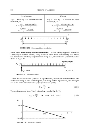
                  Shear Force and Bending Moment Distributions.  For the simply-supported beam with
                  a uniformly distributed load (w) acting across the entire beam, shown in Fig. 2.32, which
                  has the balanced free-body-diagram shown in Fig. 2.33, the shear force (V ) distribution is
                  shown in Fig. 2.34.
                                                                   w (force/length)
                       A  = 0
                        x

                             A  = wL /2                                B  = wL/2
                                                                        y
                              y
                       FIGURE 2.33  Free-body-diagram.
                    Note that the shear force (V ) starts at a positive (wL/2) at the left end of the beam and
                  decreases linearly to zero at the midpoint, continuing on to a negative (wL/2) at the right
                  end of the beam. The shear force (V ) is given by Eq. (2.18).
                                                 wL
                                             V =    − wx                       (2.18)
                                                  2
                  The maximum shear force (V max ) is therefore given by Eq. (2.19).
                                          wL
                                   V max =      at  x = 0 and  x = L           (2.19)
                                          2
                        V
                          wL/2

                                 +
                            0                                               x
                                                 L/2                    L
                                                                  –
                         –wL/2

                        FIGURE 2.34  Shear force diagram.
   69   70   71   72   73   74   75   76   77   78   79