
Page 75 - Marks Calculation for Machine Design
P. 75
P1: Sanjay
January 4, 2005
16:18
Brown˙C02
Brown.cls
57
BEAMS
The bending moment distribution is given by Eq. (2.20) for the values of the distance (x)
from the left end of the beam. (Always measure the distance (x) from the left end of any
beam, never from the right end.)
wx
M = (L − x) (2.20)
2
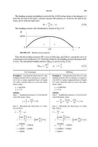
The bending moment (M) distribution is shown in Fig. 2.35.
M
2
wL /8
+ +
0 x
L/2 L
FIGURE 2.35 Bending moment diagram.
Note that the bending moment (M) is zero at both ends, and follows a parabolic curve to
a maximum at the midpoint (L/2). From the midpoint, the bending moment decreases back
to zero. The maximum bending moment (M max ) is given by Eq. (2.21).
wL 2 L
M max = at x = (2.21)
8 2
U.S. Customary SI/Metric
Example 2. Calculate the shear force (V ) and Example 2. Calculate the shear force (V ) and
bending moment (M) at a distance (x) equal to bending moment (M) at a distance (x) equal to
(L/3) for a simply-supported beam of length (3L/10) for a simply-supported beam of length
(L) with a uniform load (w) across the entire (L) with a uniform load (w) across the entire
beam, where beam, where
w = 400 lb/ft w = 6,000 N/m
L = 15 ft L = 5m
solution solution
Step 1. Establish the distance (x) from the left Step 1. Establish the distance (x) from the left
end of the beam, where end of the beam, where
L 15 ft 3L 3(5m) 15 m
x = = = 5ft x = = = = 1.5m
3 3 10 10 10
Step 2. Determine the shear force (V ) from Step 2. Determine the shear force (V ) from
Eq. (2.18) as Fig. 2.18 as
wL wL
V = − wx V = − wx
2 2
lb N
400 (15 ft) 6,000 (5m)
ft lb m N
= − 400 (5ft) = − 6,000 (1.5m)
2 ft 2 m
6,000 lb 30,000 N
= − 2,000 lb = − 9,000 N
2 2
= 3,000 lb − 2,000 lb = 15,000 N − 9,000 N
= 1,000 lb = 6,000 N