Page 80 - Marks Calculation for Machine Design
P. 80

P1: Sanjay
                          January 4, 2005
                 Brown˙C02
        Brown.cls
                  62
                            U.S. Customary 16:18  STRENGTH OF MACHINES  SI/Metric
                  Step 2. From Fig. 2.38 calculate the roller  Step 2. From Fig. 2.38 calculate the roller
                  reaction (B y ) as                 reaction (B y ) as
                            wL   (750 lb/ft)(6ft)            wL  (10,000 N/m)(1.8m)
                        B y =  =                        B y =  =
                             3       3                       3          3
                            4,500 lb                         18,000 lb
                          =       = 1,500 lb               =       = 6,000 N
                              3                                3
                                                                       w
                             A                                          B


                                                  L
                             FIGURE 2.39  Concentrated force at midpoint.

                  Shear Force and Bending Moment Distributions. For the simply-supported beam with a
                  triangular distributed load (w) acting from left to right across the beam shown in Fig. 2.39,
                  which has the balanced free-body-diagram shown in Fig. 2.40, the shear force (V ) distri-
                  bution is shown in Fig. 2.41.
                                                                       w


                        A  = 0
                         x

                              A  = wL/6                                B  = wL/3
                                                                        y
                               y
                        FIGURE 2.40  Free-body-diagram.

                         V
                          wL/6
                                      +
                             0                                             x
                                                                       L
                                                                 –
                                       0.577 L

                         –wL/3

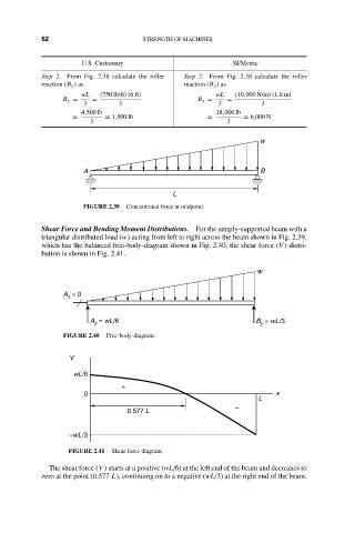
                         FIGURE 2.41  Shear force diagram.
                    The shear force (V ) starts at a positive (wL/6) at the left end of the beam and decreases to
                  zero at the point (0.577 L), continuing on to a negative (wL/3) at the right end of the beam.
   75   76   77   78   79   80   81   82   83   84   85