
Page 83 - Marks Calculation for Machine Design
P. 83
P1: Sanjay
January 4, 2005
16:18
Brown.cls
Brown˙C02
U.S. Customary BEAMS SI/Metric 65
Step 3. Calculate the maximum bending Step 3. Calculate the maximum bending
moment (M max ) from Eq. (2.27) as moment (M max ) from Eq. (2.27) as
wL 2 (750 1b/ft)(6ft) 2 wL 2 (10,000 N/m)(1.8m) 2
M max = √ = √ M max = √ = √
9 3 9 3 9 3 9 3
27,000 ft · lb 32,400 N · m
= = 1,732 ft · lb = = 2,078 N · m
15.59 15.59
Step 4. Figure 2.42 shows that this maximum Step 4. Figure 2.42 shows that this maximum
bending moment (M max ) of 1,732 ft · lb is bending moment (M max ) of 2,078 N · mis
located at located at
L L
x = √ = 0.577 L x = √ = 0.577 L
3 3
L L
= 0.577 (6ft) = 3.46 ft > = 0.577 (1.8m) = 1.04 m >
2 2
from the left end of the beam. from the left end of the beam.
w
A B
∆
L
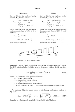
FIGURE 2.43 Beam deflection diagram.
Deflection. For this loading configuration, the deflection ( ) along the beam is shown in
Fig. 2.43, and given by Eq. (2.28) for values of the distance (x) from the left end of the
beam,
wx 4 2 2 4
= (7L − 10L x + 3x ) (2.28)
360 EIL
where = deflection of beam (positive downward)
w = applied triangular load
x = distance from left end of beam
L = length of beam
E = modulus of elasticity of beam material
I = area moment of inertia of cross-sectional area about axis through centroid
The maximum deflection ( max ) caused by this loading configuration is given by
Eq. (2.29),
wL 4
max = 0.00652 at x = 1 − 8 15 L ≈ (0.52) L (2.29)
EI
located at the point (approximately 0.52 L) from the left end of the beam.