Page 85 - Marks Calculation for Machine Design
P. 85

P1: Sanjay
                                      16:18
                          January 4, 2005
                 Brown˙C02
        Brown.cls
                              U.S. Customary     BEAMS            SI/Metric        67
                    solution                           solution
                    Step 1. Calculate the maximum deflection  Step 1. Calculate the maximum deflection
                    from Eq. (2.29).                   from Eq. (2.29).
                                 wL 4                              wL 4
                        max = 0.00652                    max = 0.00652
                                 (EI)                              (EI)
                                   (750 lb/ft)(6ft) 4               (10,000 N/m)(1.8m) 4
                          = (0.00652)                      = (0.00652)
                                                                            6
                                                                                2
                                             2
                                         6
                                  (5.83 × 10 lb · ft )               (2.27 × 10 N · m )
                                        5
                                                                          5
                                  9.72 × 10 lb · ft 3               1.05 × 10 N · m 3
                          = (0.00652)                      = (0.00652)    6    2
                                        6
                                  5.83 × 10 lb · ft 2               2.27 × 10 N · m
                          = (0.00652)(0.1667 ft)           = (0.00652)(0.0462 m)
                                    12 in                            100 cm
                          = 0.00109 ft ×  = 0.013 in ↓     = 0.0003 m ×    = 0.030 cm ↓
                                     ft                                m
                     The location of this maximum deflection  The location of this maximum deflection
                    occurs just to the right of the midpoint of the  occurs just to the right of the midpoint of the
                    beam, approximately at (0.52 L).   beam, approximately at (0.52 L).
                          = 0.52 L = (0.52)(6ft) = 3.12 ft  = 0.52 L = (0.52)(1.8m) = 0.94 m
                      x   max                           x   max
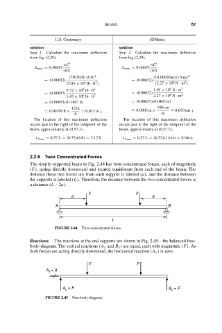
                    2.2.6 Twin Concentrated Forces
                    The simply-supported beam in Fig. 2.44 has twin concentrated forces, each of magnitude
                    (F), acting directly downward and located equidistant from each end of the beam. The
                    distance these two forces are from each support is labeled (a), and the distance between
                    the supports is labeled (L). Therefore, the distance between the two concentrated forces is
                    a distance (L – 2a).
                                           F                 F
                                    a                              a
                              A                                           B
                                                    L
                              FIGURE 2.44  Twin concentrated forces.

                    Reactions.  The reactions at the end supports are shown in Fig. 2.45—the balanced free-
                    body-diagram. The vertical reactions (A y and B y ) are equal, each with magnitude (F).As
                    both forces are acting directly downward, the horizontal reaction (A x ) is zero.

                                           F                 F
                          A  = 0
                           x

                                 A  = F                                   B  = F
                                  y
                                                                           y
                          FIGURE 2.45  Free-body-diagram.
   80   81   82   83   84   85   86   87   88   89   90