
Page 97 - Marks Calculation for Machine Design
P. 97
P1: Sanjay
16:18
January 4, 2005
Brown.cls
Brown˙C02
U.S. Customary BEAMS SI/Metric 79
solution solution
Step 1. Calculate the maximum upward Step 1. Calculate the maximum upward
deflection ( max ) from Eq. (2.39). deflection ( max ) from Eq. (2.39).
FaL 2 FaL 2
max = √ max = √
9 3 EI 9 3 EI
(450 lb)(1ft)(3ft) 2 (2,000 N)(0.3m)(1m) 2
= √ = √
2
9 3 (2.5 × 10 lb · ft ) 9 3 (1.02 × 10 N · m )
2
6
6
4,050 lb · ft 3 600 N · m 3
= =
7
7
3.9 × 10 lb · ft 2 1.59 × 10 N · m 2
12 in 100 cm
= 0.0001 ft × = 0.000038 m ×
ft m
= 0.0012 in ↑ = 0.0038 cm ↑
Step 2. From Eq. (2.39) the location of the Step 2. From Eq. (2.39) the location of the
maximum upward deflection is maximum upward deflection is
L 3ft L 1m
= √ = √ = √ = √
x max x max
3 3 3 3
= 1.73 ft = 0.577 m
L 3ft L 1m
> = = 1.5ft > = = 0.5m
2 2 2 2
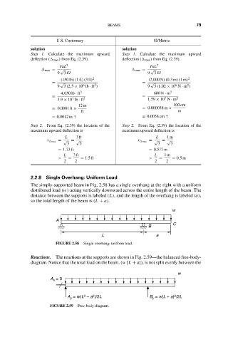
2.2.8 Single Overhang: Uniform Load
The simply-supported beam in Fig. 2.58 has a single overhang at the right with a uniform
distributed load (w) acting vertically downward across the entire length of the beam. The
distance between the supports is labeled (L), and the length of the overhang is labeled (a),
so the total length of the beam is (L + a).
w
A
C
B
L a
FIGURE 2.58 Single overhang: uniform load.
Reactions. The reactions at the supports are shown in Fig. 2.59—the balanced free-body-
diagram. Notice that the total load on the beam, (w [L + a]), is not split evenly between the
w
A = 0
x
2
2
2
A = w(L – a )/2L B = w(L + a) /2L
y
y
FIGURE 2.59 Free-body-diagram.