
Page 116 - Marks Calculation for Machine Design
P. 116
P1: Sanjay
January 4, 2005
Brown˙C02
Brown.cls
98
A 16:18 STRENGTH OF MACHINES B
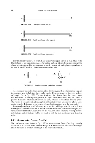
FIGURE 2.79 Cantilevered beam: free end.
A B
FIGURE 2.80 Cantilevered beam: roller support.
A B
FIGURE 2.81 Cantilevered beam: pin support.
For the idealized symbol at point A, the cantilever support shown in Fig. 2.82a looks
like the beam is just stuck to the side of the vertical wall, but it is not. It represents the ability
of this type of support, like a pin support, to restrict motion left and right and up and down,
but also to restrict rotation, clockwise or counterclockwise.
A
A x
A y C A
(a) (b)
FIGURE 2.82 Cantilever support symbol and reactions.
As a cantilever support restricts motion in two directions, as well as rotation at the support,
the reactions must include two forces and a couple. These are shown as forces A x and A y ,
and couple C A , in Fig. 2.82b. The magnitude and direction of these forces and couple
will depend on the loading configuration, so again, until determined, they are shown in
positive directions, where counterclockwise (ccw) rotation is considered positive. (Note:
The symbol C is used to indicate a couple to differentiate it from a moment of a force about
a point, usually designated by an M, even though both quantities have the same units.)
Examples involving several different types of loadings will be presented for each of these
three types of cantilevered beams, to include concentrated forces, concentrated couples, and
various distributed loads. Calculations for the reactions, shear force and bending moment
distributions, and deflections will be provided in both the U.S. Customary and SI/metric
units.
2.3.1 Concentrated Force at Free End
The cantilevered beam shown in Fig. 2.83 has a concentrated force (F) acting vertically
downward at its free end that is on the left at point A. The cantilever reaction is on the right
end of the beam, at point B. The length of the beam is labeled (L).