
Page 124 - Marks Calculation for Machine Design
P. 124
P1: Sanjay
January 4, 2005
16:18
Brown.cls
Brown˙C02
106
STRENGTH OF MACHINES
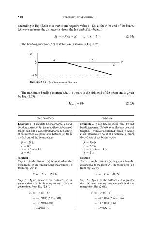
according to Eq. (2.64) to a maximum negative value (−Fb) at the right end of the beam.
(Always measure the distance (x) from the left end of any beam.)
M =−F (x − a) a ≤ x ≤ L (2.64)
The bending moment (M) distribution is shown in Fig. 2.95.
M
a b
0 x
L
–
–Fb
FIGURE 2.95 Bending moment diagram.
The maximum bending moment (M max ) occurs at the right end of the beam and is given
by Eq. (2.65).
M max = Fb (2.65)
U.S. Customary SI/Metric
Example 2. Calculate the shear force (V ) and Example 2. Calculate the shear force (V ) and
bending moment (M) for a cantilevered beam of bending moment (M) for a cantilevered beam of
length (L) with a concentrated force (F) acting length (L) with a concentrated force (F) acting
at an intermediate point, at a distance (x) from at an intermediate point, at a distance (x) from
the left end of the beam, where the left end of the beam, where
F = 150 lb F = 700 N
L = 8ft L = 2.5 m
a = 3 ft, b = 5ft a = 1m, b = 1.5 m
x = 6ft x = 2m
solution solution
Step 1. As the distance (x) is greater than the Step 1. As the distance (x) is greater than the
distance (a) to the force (F), the shear force (V ) distance (a) to the force (F), the shear force (V )
from Fig. 2.94 is from Fig. 2.94 is
V =−F =−150 lb V =−F =−700 N
Step 2. Again, because the distance (x) is Step 2. Again, as the distance (x) is greater
greater than (a), the bending moment (M) is than (a), the bending moment (M) is deter-
determined from Eq. (2.64). mined from Eq. (2.64).
M =−F (x − a) M =−F (x − a)
=−(150 lb)(6ft − 3ft) =−(700 N)(2m − 1m)
=−(150 ft)(3ft) =−(700 N)(1m)
=−450 ft · lb =−700 N · m