Page 274 - Marks Calculation for Machine Design
P. 274

P1: Shibu
                          January 4, 2005
                                      14:56
                 Brown˙C06
        Brown.cls
                  256
                                           STRENGTH OF MACHINES
                                                         Biaxial where
                                                          s  = s  > 0
                                                              2
                                                           1
                                                s 2
                               Boundary of allowable
                                  combinations         3
                                               210
                                                                     Biaxial where
                                                               2     s 1  = 2s  > 0
                                                                          2
                                                                        s
                         –630                             210            1
                                                                1
                                              –30                Uniaxial where
                                                              4   s  > 0, s  = 0
                                                                   1
                                                                        2
                                                          5
                                                      Pure shear where
                                              –630     s  > 0, s  = –s 1
                                                             2
                                                       1
                                                              Scale: 35 MPa × 35 MPa

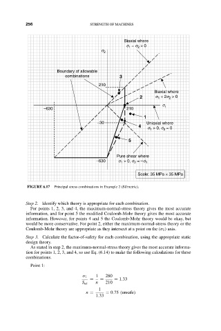
                   FIGURE 6.17  Principal stress combinations in Example 2 (SI/metric).


                  Step 2. Identify which theory is appropriate for each combination.
                    For points 1, 2, 3, and 4, the maximum-normal-stress theory gives the most accurate
                  information, and for point 5 the modified Coulomb-Mohr theory gives the most accurate
                  information. However, for points 4 and 5 the Coulomb-Mohr theory would be okay, but
                  would be more conservative. For point 2, either the maximum-normal-stress theory or the
                  Coulomb-Mohr theory are appropriate as they intersect at a point on the (σ 1 ) axis.
                  Step 3. Calculate the factor-of-safety for each combination, using the appropriate static
                  design theory.
                    As stated in step 2, the maximum-normal-stress theory gives the most accurate informa-
                  tion for points 1, 2, 3, and 4, so use Eq. (6.14) to make the following calculations for these
                  combinations.
                    Point 1:

                                         σ 1  1  280
                                           =   =     = 1.33
                                        S ut  n  210
                                               1
                                          n =     = 0.75 (unsafe)
                                              1.33
   269   270   271   272   273   274   275   276   277   278   279