Page 271 - Marks Calculation for Machine Design
P. 271

P1: Shibu
                          January 4, 2005
                                      14:56
        Brown.cls
                 Brown˙C06
                                     STATIC DESIGN AND COLUMN BUCKLING
                                                          Biaxial where           253
                                                           s  = s  > 0
                                                                2
                                                            1
                                                 s 2
                                Boundary of allowable
                                   combinations          3
                                                 30
                                                                      Biaxial where
                                                                2      s 1  = 2s  > 0
                                                                            2
                                                                         s
                            –90                            30             1
                                                                  1
                                                –30                Uniaxial where
                                                                4   s  > 0, s  = 0
                                                                    1
                                                                          2
                                                            5

                                                       Pure shear where
                                                –90     s  > 0, s  = –s 1
                                                         1
                                                              2
                                                                Scale: 5 kpsi ¥ 5 kpsi

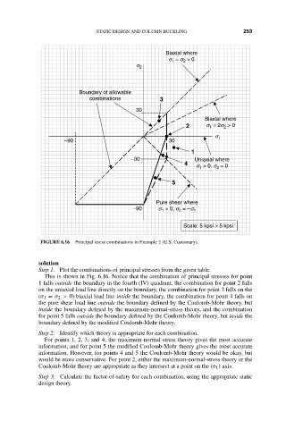
                    FIGURE 6.16  Principal stress combinations in Example 2 (U.S. Customary).


                    solution
                    Step 1. Plot the combinations of principal stresses from the given table.
                      This is shown in Fig. 6.16. Notice that the combination of principal stresses for point
                    1 falls outside the boundary in the fourth (IV) quadrant, the combination for point 2 falls
                    on the uniaxial load line directly on the boundary, the combination for point 3 falls on the
                    (σ 1 = σ 2 > 0) biaxial load line inside the boundary, the combination for point 4 falls on
                    the pure shear load line outside the boundary defined by the Coulomb-Mohr theory, but
                    inside the boundary defined by the maximum-normal-stress theory, and the combination
                    for point 5 falls outside the boundary defined by the Coulomb-Mohr theory, but inside the
                    boundary defined by the modified Coulomb-Mohr theory.
                    Step 2. Identify which theory is appropriate for each combination.
                      For points 1, 2, 3, and 4, the maximum-normal-stress theory gives the most accurate
                    information, and for point 5 the modified Coulomb-Mohr theory gives the most accurate
                    information. However, for points 4 and 5 the Coulomb-Mohr theory would be okay, but
                    would be more conservative. For point 2, either the maximum-normal-stress theory or the
                    Coulomb-Mohr theory are appropriate as they intersect at a point on the (σ 1 ) axis.
                    Step 3. Calculate the factor-of-safety for each combination, using the appropriate static
                    design theory.
   266   267   268   269   270   271   272   273   274   275   276