
Page 267 - Marks Calculation for Machine Design
P. 267
P1: Shibu
14:56
January 4, 2005
Brown˙C06
Brown.cls
STATIC DESIGN AND COLUMN BUCKLING
The mathematical expressions representing a safe design according to the Coulomb-Mohr
theory are given in Eq. (6.15), 249
σ 1 σ 2 σ 2 σ 1
− < 1or − < 1 (6.15)
S ut S uc S ut S uc
where the first expression in Eq. (6.15) specifies the line in the fourth (IV) quadrant and the
second expression specifies the line, only mathematically, in the second (II) quadrant.
The factor-of-safety (n) for this theory is given in Eq. (6.16), which replaces the inequality
signs in Eq. (6.15) with equal to signs to give
σ 1 σ 2 1 σ 2 σ 1 1
− = or − = (6.16)
S ut S uc n S ut S uc n
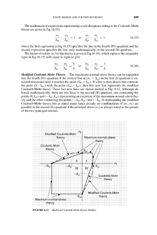
Modified Coulomb-Mohr Theory. The maximum-normal-stress theory can be expanded
into the fourth (IV) quadrant if the vertical line at (σ 1 = S ut )inthe first (I) quadrant is ex-
tended downward until it reaches the point (S ut ,−S ut ). If a line is then drawn that connects
the point (0,−S uc ) with the point (S ut ,−S ut ), then this new line represents the modified
Coulomb-Mohr theory. These two new lines are shown dashed in Fig. 6.12. Although al-
lowed mathematically, there are two lines in the second (II) quadrant, one connecting the
points (0,S ut ) and (−S ut ,S ut ) representing an extension of the maximum-normal-stress the-
ory and the other connecting the points (−S ut ,S ut ) and (−S uc ,0) representing the modified
Coulomb-Mohr theory, but as stated many times already, no combinations of (σ 1 , σ 2 ) are
possible in the second (II) quadrant if the principal stress (σ 1 ) is always noted as the greater
of the two principal stresses.
s 2
Modified Coulomb-Mohr
theory Maximum-normal-stress
theory
Coulomb-Mohr
theory
S ut
II I
s 1
–S uc –S ut S ut
III IV
–S ut Coulomb-Mohr
theory
Modified Coulomb-Mohr
–S uc theory
Maximum-normal-stress
theory
FIGURE 6.12 Modified Coulomb-Mohr theory (brittle).