
Page 266 - Marks Calculation for Machine Design
P. 266
P1: Shibu
January 4, 2005
14:56
Brown.cls
Brown˙C06
STRENGTH OF MACHINES
248
The boundaries at the vertical line, (σ 1 =−S uc ), and the horizontal line, (σ 2 = S ut ), are
permissible by mathematics but are not allowable combinations of (σ 1 ,σ 2 ).
The factor-of-safety (n) for this theory is given in Eq. (6.14), which replaces the inequality
signs in Eq. (6.13) with equal to signs and are then rearranged to give
σ 1 1 σ 2 1
= or = (6.14)
S ut n −S uc n
The factor-of-safety (n) in either expression of Eq. (6.14) represents how close the com-
bination of the principal stresses (σ 1 ,σ 2 ) is to the boundary defined by the theory. A factor-
of-safety much greater than 1 means the (σ 1 ,σ 2 ) combination is not only inside the boundary
of the theory but far from it. A factor-of-safety equal to (1) means the combination is on
the boundary. Any factor-of-safety less than 1 is outside the boundary and represents an
unsafe static loading condition.
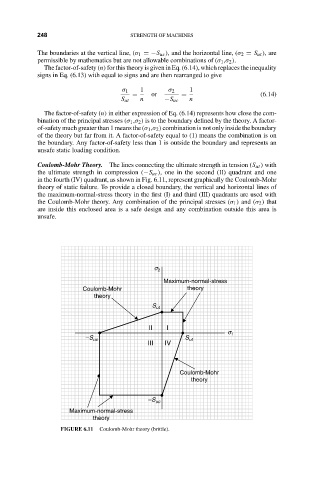
Coulomb-Mohr Theory. The lines connecting the ultimate strength in tension (S ut ) with
the ultimate strength in compression (−S uc ), one in the second (II) quadrant and one
in the fourth (IV) quadrant, as shown in Fig. 6.11, represent graphically the Coulomb-Mohr
theory of static failure. To provide a closed boundary, the vertical and horizontal lines of
the maximum-normal-stress theory in the first (I) and third (III) quadrants are used with
the Coulomb-Mohr theory. Any combination of the principal stresses (σ 1 ) and (σ 2 ) that
are inside this enclosed area is a safe design and any combination outside this area is
unsafe.
s 2
Maximum-normal-stress
Coulomb-Mohr theory
theory
S ut
II I
s 1
–S uc S ut
III IV
Coulomb-Mohr
theory
–S uc
Maximum-normal-stress
theory
FIGURE 6.11 Coulomb-Mohr theory (brittle).