
Page 265 - Marks Calculation for Machine Design
P. 265
P1: Shibu
14:56
January 4, 2005
Brown.cls
Brown˙C06
STATIC DESIGN AND COLUMN BUCKLING
Forbrittlematerials,therearethreestaticdesigntheoriesthatfittheavailableexperimental
data on whether the combinations of (σ 1 ,σ 2 ) for a machine element are safe: 247
Maximum-normal-stress theory
Coulomb-Mohr theory
Modified Coulomb-Mohr theory
Each of these three theories will be discussed separately, followed by the appropriate
recommendations as to which theory is best for every possible combination of the principal
stresses (σ 1 ,σ 2 ). Remember, combinations in the second (II) quadrant are impossible if it is
assumed that the maximum principal stress (σ 1 ) is always greater than or at least equal to
the minimum principal stress (σ 2 ), even though the mathematical expressions and graphical
representations that will be shown allow this combination.
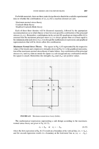
Maximum-Normal-Stress Theory. The square in Fig. 6.10 represented by the respective
values of the tensile and compressive strengths shown in Fig. 6.1 is the graphical representa-
tion of the maximum-normal-stress theory of static failure. Any combination of the principal
stresses (σ 1 ) and (σ 2 ) that are inside the square is a safe design and any combination outside
the square is unsafe. Remember, the strengths (S ut )and (S uc ) are positive values.
s 2
S ut
II I
s 1
–S uc S ut
III IV
–S uc
FIGURE 6.10 Maximum-normal-stress theory (brittle).
The mathematical expressions representing a safe design according to the maximum-
normal-stress theory are given in Eq. (6.13),
σ 1 < S ut or σ 2 > − S uc (6.13)
where the first expression in Eq. (6.13) results in a boundary at the vertical line, (σ 1 = S ut ),
and the second expression results in a boundary at the horizontal line at, (σ 2 =−S uc ).