
Page 268 - Marks Calculation for Machine Design
P. 268
P1: Shibu
January 4, 2005
14:56
Brown.cls
Brown˙C06
STRENGTH OF MACHINES
250
The mathematical expressions representing a safe design according to the modified
Coulomb-Mohr theory are given in Eq. (6.17),
σ 1 S ut σ 2 σ 2 S ut σ 1
1 − − < 1or 1 − − < 1 (6.17)
S ut S uc S uc S ut S uc S uc
where the first expression in Eq. (6.17) specifies the line in the fourth (IV) quadrant con-
necting the points (0,−S uc ) and (S ut ,−S ut ), and the second expression specifies the line in
the second (II) quadrant connecting the points (−S uc ,0) and (−S ut ,S ut ).
The factor-of-safety (n) for this theory is given in Eq. (6.18), which replaces the inequality
signs in Eq. (6.17) with equal to signs to give
σ 1 S ut σ 2 1 σ 2 S ut σ 1 1
1 − − = or 1 − − = (6.18)
S ut S uc S uc n S ut S uc S uc n
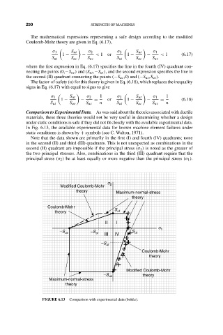
Comparison to Experimental Data. As was said about the theories associated with ductile
materials, these three theories would not be very useful in determining whether a design
under static conditions is safe if they did not fit closely with the available experimental data.
In Fig. 6.13, the available experimental data for known machine element failures under
static conditions is shown by + symbols (see C. Walton, 1971).
Note that the data shown are primarily in the first (I) and fourth (IV) quadrants; none
in the second (II) and third (III) quadrants. This is not unexpected as combinations in the
second (II) quadrant are impossible if the principal stress (σ 1 ) is noted as the greater of
the two principal stresses. Also, combinations in the third (III) quadrant require that the
principal stress (σ 2 ) be at least equally or more negative than the principal stress (σ 1 ).
s
Modified Coulomb-Mohr 2
theory Maximum-normal-stress
theory
Coulomb-Mohr
theory S ut +
+
II I +
+ s 1
–S uc –S ut III IV + S ut
+
–S ut + +
+ Coulomb-Mohr
+ theory
+
+
+ Modified Coulomb-Mohr
–S uc theory
Maximum-normal-stress
theory
FIGURE 6.13 Comparison with experimental data (brittle).