Page 270 - Marks Calculation for Machine Design
P. 270

P1: Shibu
                                      14:56
                          January 4, 2005
                 Brown˙C06
        Brown.cls
                                           STRENGTH OF MACHINES
                  252
                                                      Biaxial where
                                                      s = s > 0
                                                          2
                                                       1
                                                s 2
                                Boundary of allowable
                                   combinations
                                                S ut
                                                                 Biaxial where
                                                                 s = 2s > 0
                                                        S ut      1   2
                                                                    s 1
                             –S uc
                                              –S ut             Uniaxial where
                                                                s > 0, s = 0
                                                                      2
                                                                 1
                                                     Pure shear where
                                                     s > 0, s = –s 1
                                                           2
                                                      1
                                               –S uc
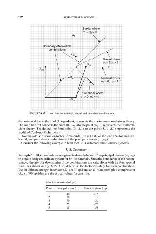
                         FIGURE 6.15  Load lines for uniaxial, biaxial, and pure shear combinations.
                  the horizontal line in the third (III) quadrant, represents the maximum-normal-stress theory.
                  The solid line that connects the point (0,−S uc ) to the point (S ut ,0) represents the Coulomb-
                  Mohr theory. The dotted line from point (0,−S uc ) to the point (S ut ,−S ut ) represents the
                  modified Coulomb-Mohr theory.
                    To conclude the discussion for brittle materials, Fig. 6.15 shows the load lines for uniaxial,
                  biaxial, and pure shear combinations of the principal stresses (σ 1 , σ 2 ).
                    Consider the following example in both the U.S. Customary and SI/metric systems.
                                             U.S. Customary
                  Example 2. Plot the combinations given in the table below of the principal stresses (σ 1 , σ 2 )
                  on a static design coordinate system for brittle materials. Show the boundaries of the recom-
                  mended theories for determining if the combinations are safe, along with the four special
                  load lines shown in Fig. 6.15. Also, determine the factor-of-safety for each combination.
                  Use an ultimate strength in tension (S ut ) of 30 kpsi and an ultimate strength in compression
                  (S uc ) of 90 kpsi that are the typical values for cast iron.

                                  Principal stresses (in kpsi)
                                  Point  Principal stress (σ 1 )  Principal stress (σ 2 )
                                   1         40             −15
                                   2         30               0
                                   3         20              20
                                   4         25             −25
                                   5         15             −55
   265   266   267   268   269   270   271   272   273   274   275