
Page 276 - Marks Calculation for Machine Design
P. 276
P1: Shibu
January 4, 2005
14:56
Brown.cls
Brown˙C06
258
STRENGTH OF MACHINES
where the factors-of-safety found are less than 1 and indicates an unsafe static condition.
This is why the Coulomb-Mohr theory is more conservative or more restrictive in this region
of the diagram.
6.1.3 Stress-Concentration Factors
The normal (σ) and shear (τ) stress formulas presented in Chap. 1 for fundamental loadings
and Chap. 3 for advanced loadings, and that were summarized in Tables 4.1 and 4.2 in
Chap. 4 on combined loadings, were developed for machine elements having uniform
geometric features. Adding such things as a hole or notches to a bar in tension or bending,
or changing the diameter of a shaft in torsion or bending, produce what are called stress
concentrations in the machine element at the change in geometry. Manufacturing processes
can also create stress concentrations, such as shoulder fillets at the transition between two
different diameters of a shaft. Even the welding process can produce significant stress
concentrations.
As it turns out, stress concentrations are not a problem for machine elements made of
ductile materials as the material will deform appropriately to adjust to these stress concen-
trations. However, machine elements made of brittle materials are very susceptible to stress
concentrations, and therefore, stress-concentration factors should always be incorporated
in the stress calculations.
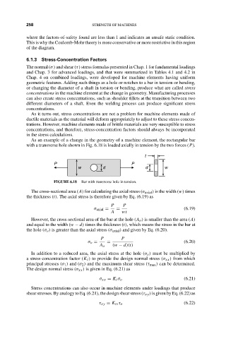
As an example of a change in the geometry of a machine element, the rectangular bar
with a transverse hole shown in Fig. 6.18 is loaded axially in tension by the two forces (P).
t
P P
w d d w
FIGURE 6.18 Bar with transverse hole in tension.
The cross-sectional area (A) for calculating the axial stress (σ axial ) is the width (w) times
the thickness (t). The axial stress is therefore given by Eq. (6.19) as
P P
σ axial = = (6.19)
A wt
However, the cross-sectional area of the bar at the hole (A o ) is smaller than the area (A)
and equal to the width (w − d) times the thickness (t), which means the stress in the bar at
the hole (σ o ) is greater than the axial stress (σ axial ) and given by Eq. (6.20).
P P
σ o = = (6.20)
A o (w − d)(t)
In addition to a reduced area, the axial stress at the hole (σ o ) must be multiplied by
a stress-concentration factor (K t ) to provide the design normal stress (σ xx ) from which
principal stresses (σ 1 ) and (σ 2 ) and the maximum shear stress (τ max ) can be determined.
The design normal stress (σ xx ) is given in Eq. (6.21) as
σ xx = K t σ o (6.21)
Stress concentrations can also occur in machine elements under loadings that produce
shear stresses. By analogy to Eq. (6.21), the design shear stress (τ xy ) is given by Eq. (6.22) as
τ xy = K ts τ o (6.22)