
Page 280 - Marks Calculation for Machine Design
P. 280
P1: Shibu
January 4, 2005
14:56
Brown.cls
Brown˙C06
STRENGTH OF MACHINES
262
the critical stress is reduced by the inverse square, meaning that if the length is doubled the
critical stress is reduced by a factor of 4.
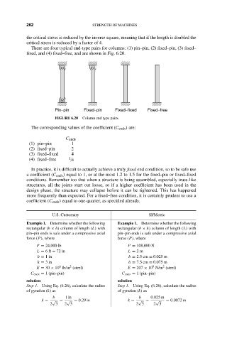
There are four typical end-type pairs for columns: (1) pin–pin, (2) fixed–pin, (3) fixed–
fixed, and (4) fixed–free, and are shown in Fig. 6.20.
Pin–pin Fixed–pin Fixed–fixed Fixed–free
FIGURE 6.20 Column end type pairs.
The corresponding values of the coefficient (C ends ) are:
C ends
(1) pin–pin 1
(2) fixed–pin 2
(3) fixed–fixed 4
(4) fixed–free 1 / 4
In practice, it is difficult to actually achieve a truly fixed end condition, so to be safe use
a coefficient (C ends ) equal to 1, or at the most 1.2 to 1.5 for the fixed–pin or fixed–fixed
conditions. Remember too that when a structure is being assembled, especially truss-like
structures, all the joints start out loose, so if a higher coefficient has been used in the
design phase, the structure may collapse before it can be tightened. This has happened
more frequently than expected. For a fixed–free condition, it is certainly prudent to use a
coefficient (C ends ) equal to one-quarter, as specified already.
U.S. Customary SI/Metric
Example 1. Determine whether the following Example 1. Determine whether the following
rectangular (b × h) column of length (L) with rectangular (b × h) column of length (L) with
pin–pin ends is safe under a compressive axial pin–pin ends is safe under a compressive axial
force (P), where force (P), where
P = 24,000 lb P = 108,000 N
L = 6ft = 72 in L = 2m
b = 1in b = 2.5 cm = 0.025 m
h = 3in h = 7.5 cm = 0.075 m
2
6
9
2
E = 30 × 10 lb/in (steel) E = 207 × 10 N/m (steel)
C ends = 1 (pin–pin) C ends = 1 (pin–pin)
solution solution
Step 1. Using Eq. (6.26), calculate the radius Step 1. Using Eq. (6.26), calculate the radius
of gyration (k) as of gyration (k) as
b 1in b 0.025 m
k = √ = √ = 0.29 in k = √ = √ = 0.0072 m
2 3 2 3 2 3 2 3