
Page 334 - Marks Calculation for Machine Design
P. 334
P1: Shashi
January 4, 2005
15:4
Brown.cls
Brown˙C07
316
STRENGTH OF MACHINES
Step 1F. Using the test specimen endurance limit (S ) found in step 1E, and the modifying
e
factors found in steps 1A through 1D, calculate the endurance limit (S e ) for the solid shaft
using the Marin equation for combined loading in Eq. (7.35) as
S e = k a k b (1)k d S = (0.86)(0.87)(1)(1.020)(264.6MPa)
e
= (0.763)(264.6MPa) = 202 MPa
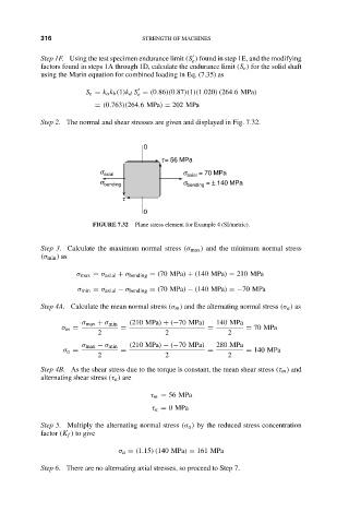
Step 2. The normal and shear stresses are given and displayed in Fig. 7.32.
0
t = 56 MPa
s axial s axial = 70 MPa
s bending s bending = ± 140 MPa
t
0
FIGURE 7.32 Plane stress element for Example 4 (SI/metric).
Step 3. Calculate the maximum normal stress (σ max ) and the minimum normal stress
(σ min ) as
σ max = σ axial + σ bending = (70 MPa) + (140 MPa) = 210 MPa
σ min = σ axial − σ bending = (70 MPa) − (140 MPa) =−70 MPa
Step 4A. Calculate the mean normal stress (σ m ) and the alternating normal stress (σ a ) as
σ max + σ min (210 MPa) + (−70 MPa) 140 MPa
σ m = = = = 70 MPa
2 2 2
σ max − σ min (210 MPa) − (−70 MPa) 280 MPa
σ a = = = = 140 MPa
2 2 2
Step 4B. As the shear stress due to the torque is constant, the mean shear stress (τ m ) and
alternating shear stress (τ a ) are
τ m = 56 MPa
τ a = 0MPa
Step 5. Multiply the alternating normal stress (σ a ) by the reduced stress concentration
factor (K f ) to give
σ a = (1.15)(140 MPa) = 161 MPa
Step 6. There are no alternating axial stresses, so proceed to Step 7.