
Page 330 - Marks Calculation for Machine Design
P. 330
P1: Shashi
Brown˙C07
Brown.cls
312
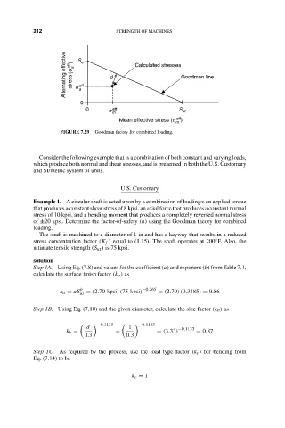
Alternating effective January 4, 2005 15:4 d STRENGTH OF MACHINES Goodman line
S e
(s eff )
Calculated stresses
a
stress
eff
s
a
0
0 s eff S ut
m
eff
Mean effective stress (s )
m
FIGURE 7.29 Goodman theory for combined loading.
Consider the following example that is a combination of both constant and varying loads,
which produce both normal and shear stresses, and is presented in both the U.S. Customary
and SI/metric system of units.
U.S. Customary
Example 1. A circular shaft is acted upon by a combination of loadings: an applied torque
that produces a constant shear stress of 8 kpsi, an axial force that produces a constant normal
stress of 10 kpsi, and a bending moment that produces a completely reversed normal stress
of ±20 kpsi. Determine the factor-of-safety (n) using the Goodman theory for combined
loading.
The shaft is machined to a diameter of 1 in and has a keyway that results in a reduced
◦
stress concentration factor (K f ) equal to (1.15). The shaft operates at 200 F. Also, the
ultimate tensile strength (S ut ) is 75 kpsi.
solution
Step 1A. Using Eq. (7.8) and values for the coefficient (a) and exponent (b) from Table 7.1,
calculate the surface finish factor (k a ) as
k a = aS b = (2.70 kpsi)(75 kpsi) −0.265 = (2.70)(0.3185) = 0.86
ut
Step 1B. Using Eq. (7.10) and the given diameter, calculate the size factor (k b ) as
−0.1133 −0.1133
d 1 −0.1133
k b = = = (3.33) = 0.87
0.3 0.3
Step 1C. As required by the process, use the load type factor (k c ) for bending from
Eq. (7.14) to be
k c = 1