
Page 331 - Marks Calculation for Machine Design
P. 331
P1: Shashi
January 4, 2005
Brown˙C07
Brown.cls
◦
Step 1D. The shaft is operating at 200 F so the temperature factor (k d ) from Eq. (7.15)
and Table 7.2 is 15:4 FATIGUE AND DYNAMIC DESIGN 313
k d = 1.020
Step 1E. Using the given ultimate tensile stress (S ut ) and the guidelines in Eq. (7.1),
calculate the test specimen endurance limit (S ) as
e
S = 0.504 S ut = (0.504)(75 kpsi) = 37.8 kpsi
e
Step 1F. Using the test specimen endurance limit (S ) found in step 1E, and the modifying
e
factors found in steps 1A through 1D, calculate the endurance limit (S e ) for the solid shaft
using the Marin equation for combined loading in Eq. (7.35) as
S e = k a k b (1)k d S = (0.86)(0.87)(1)(1.020)(37.8 kpsi)
e
= (0.763)(37.8 kpsi) = 28.8 kpsi
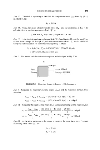
Step 2. The normal and shear stresses are given, and displayed in Fig. 7.30.
0
t = 8 kpsi
s = 10 kpsi
s axial axial
s bending s bending = ± 20 kpsi
t
0
FIGURE 7.30 Plane stress element for Example 1 (U.S. Customary).
Step 3. Calculate the maximum normal stress (σ max ) and the minimum normal stress
(σ min ) as
σ max = σ axial + σ bending = (10 kpsi) + (20 kpsi) = 30 kpsi
σ min = σ axial − σ bending = (10 kpsi) − (20 kpsi) =−10 kpsi
Step 4A. Calculate the mean normal stress (σ m ) and the alternating normal stress (σ a ) as
σ max + σ min (30 kpsi) + (−10 kpsi) 20 kpsi
σ m = = = = 10 kpsi
2 2 2
σ max − σ min (30 kpsi) − (−10 kpsi) 40 kpsi
σ a = = = = 20 kpsi
2 2 2
Step 4B. As the shear stress due to the torque is constant, the mean shear stress (τ m ) and
alternating shear stress (τ a ) are
τ m = 8 kpsi
τ a = 0 kpsi