
Page 326 - Marks Calculation for Machine Design
P. 326
P1: Shashi
15:4
January 4, 2005
Brown.cls
Brown˙C07
308
STRENGTH OF MACHINES
Justforcuriosity,whatif theendurance limitwere doubled,from 6.2 kpsi to 12.4 kpsi, how
would this change the factor-of-safety (n)? Substituting this new value for the endurance
limit (S e ) into the Goodman theory, previously calculated in step 13 above, gives a safe
value.
1 τ a τ m 3.6 kpsi 36.2 kpsi
= + = + = (0.290) + (0.600) = 0.89
n S e S us 12.4 kpsi 60.3 kpsi
1
n = = 1.12 (safe!)
0.89
SI/metric
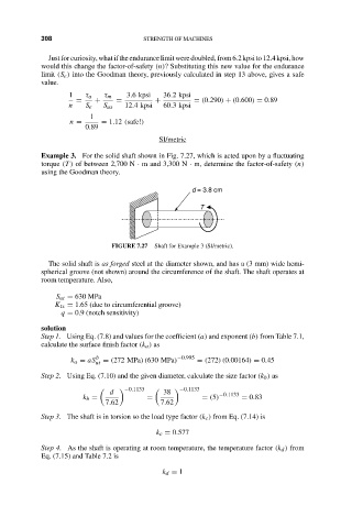
Example 3. For the solid shaft shown in Fig. 7.27, which is acted upon by a fluctuating
torque (T ) of between 2,700 N · m and 3,300 N · m, determine the factor-of-safety (n)
using the Goodman theory.
d = 3.8 cm
T
FIGURE 7.27 Shaft for Example 3 (SI/metric).
The solid shaft is as forged steel at the diameter shown, and has a (3 mm) wide hemi-
spherical groove (not shown) around the circumference of the shaft. The shaft operates at
room temperature. Also,
S ut = 630 MPa
K ts = 1.65 (due to circumferential groove)
q = 0.9 (notch sensitivity)
solution
Step 1. Using Eq. (7.8) and values for the coefficient (a) and exponent (b) from Table 7.1,
calculate the surface finish factor (k a ) as
k a = aS b = (272 MPa)(630 MPa) −0.995 = (272)(0.00164) = 0.45
ut
Step 2. Using Eq. (7.10) and the given diameter, calculate the size factor (k b ) as
−0.1133 −0.1133
d 38 −0.1133
k b = = = (5) = 0.83
7.62 7.62
Step 3. The shaft is in torsion so the load type factor (k c ) from Eq. (7.14) is
k c = 0.577
Step 4. As the shaft is operating at room temperature, the temperature factor (k d ) from
Eq. (7.15) and Table 7.2 is
k d = 1