Page 323 - Marks Calculation for Machine Design
P. 323

P1: Shashi
                          January 4, 2005
                                      15:4
                 Brown˙C07
        Brown.cls
                                        FATIGUE AND DYNAMIC DESIGN
                                                                                  305
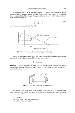
                      The Goodman theory can be used to determine if a design is safe under fluctuating
                    torsional loading; however, use the ultimate shear strength (S us ) instead of the ultimate
                    tensile strength (S ut ). This changes the equation for the factor-of-safety (n) according to
                    the Goodman theory to be
                                               τ a  τ m  1
                                                 +    =                         (7.34)
                                               S e  S us  n
                    and plotted as the straight line in Fig. 7.24.
                              Alternating shear  stress (t a ) S e a  d  Calculated stresses Goodman line

                                  t

                                  0
                                    0      t m                  S us
                                                Mean shear stress (t )
                                                              m
                            FIGURE 7.24  Goodman theory for fluctuating torsional loading.

                      Consider the following example of a solid circular shaft under fluctuating torsional load-
                    ing, in both the U.S. Customary and SI/metric system of units.

                                              U.S. Customary
                    Example 3. For the solid shaft shown in Fig. 7.25, which is acted upon by a fluctuating
                    torque (T ) of between (1,800 ft · lb) and (2,200 ft · lb), determine the factor-of-safety (n)
                    using the Goodman theory.

                                                             1 "
                                                         d = 1
                                                             2
                                                           T


                                   FIGURE 7.25  Shaft for Example 3 (U.S. Customary).

                      The solid shaft is as forged steel at the diameter shown, and has a (1/8 in) wide hemi-
                    spherical groove (not shown) around the circumference of the shaft. The shaft operates at
                    room temperature. Also,

                        S ut = 90 kpsi
                       K ts = 1.65 (due to circumferential groove)
                         q = 0.9 (notch sensitivity)
   318   319   320   321   322   323   324   325   326   327   328