
Page 318 - Marks Calculation for Machine Design
P. 318
P1: Shashi
January 4, 2005
15:4
Brown˙C07
Brown.cls
STRENGTH OF MACHINES
300
Step 9. Calculate the area (A) of the larger diameter (d 1 ) for the stepped rod as
2
π 2 π 3 2
A = d = in = 0.0276 in
1
4 4 16
Step 10. Calculate the mean axial stress (σ m ) and the alternating axial stress (σ a ) as
F m 800 lb
σ m = = = 29.0 kpsi
A 0.0276 in 2
F a 500 lb
σ a = = 2 = 18.1 kpsi
A 0.0276 in
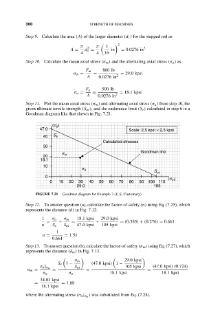
Step 11. Plot the mean axial stress (σ m ) and alternating axial stress (σ a ) from step 10, the
given ultimate tensile strength (S ut ), and the endurance limit (S e ) calculated in step 6 in a
Goodman diagram like that shown in Fig. 7.21.
)
(s a
47.0 Scale: 2.5 kpsi × 2.5 kpsi
40 S e
Calculated stresses
30
s Goodman line
20 m
18.1
10
s a S
0 ut (s )
0 10 20 30 40 50 60 70 80 90 100 110 m
29.0 105
FIGURE 7.21 Goodman diagram for Example 2 (U.S. Customary).
Step 12. To answer question (a), calculate the factor-of-safety (n) using Eq. (7.25), which
represents the distance (d) in Fig. 7.12.
1 σ a σ m 18.1 kpsi 29.0 kpsi
= + = + = (0.385) + (0.276) = 0.661
n S e S ut 47.0 kpsi 105 kpsi
1
n = = 1.51
0.661
Step 13. To answer question (b), calculate the factor-of-safety (n m ) using Eq. (7.27), which
represents the distance (d m ) in Fig. 7.13.
σ m 29.0 kpsi
S e 1 − (47.0 kpsi) 1 −
σ a | σ m S ut 105 kpsi (47.0 kpsi)(0.724)
n m = = = =
σ a σ a 18.1 kpsi 18.1 kpsi
34.03 kpsi
= = 1.88
18.1 kpsi
) was substituted from Eq. (7.28).
where the alternating stress (σ a | σ m