Page 315 - Marks Calculation for Machine Design
P. 315

P1: Shashi
                          January 4, 2005
                 Brown˙C07
        Brown.cls
                    Step 11. Calculate the area moment of inertia (I) for the rectangular cross section as
                           1   3  1   15:4 FATIGUE AND DYNAMIC DESIGN −4  4  −12  4  297
                                                   3
                       I =   bh =   (1.25 cm)(0.16 cm) = 4.27 × 10  cm = 4.27 × 10  m
                           12     12
                    Step 12. Calculate the mean bending stress (σ m ) and the alternating bending stress (σ a ) as
                                     M m c  (1.08 N · m)(0.0008 m)
                                σ m =     =                   = 202.3MPa
                                       I      4.27 × 10 −12  m 4
                                     M a c  (0.43 N · m)(0.0008 m)
                                 σ a =   =                    = 80.6MPa
                                       I      4.27 × 10 −12  m 4
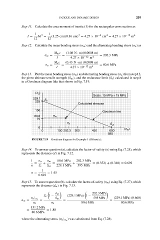
                    Step13. Plotthemeanbendingstress (σ m )andalternatingbendingstress(σ a )fromstep12,
                    the given ultimate tensile strength (S ut ), and the endurance limit (S e ) calculated in step 8
                    in a Goodman diagram like that shown in Fig. 7.19.

                           (s )
                             a
                                                           Scale: 15 MPa × 15 MPa
                          229.1  S
                           225   e
                                                  Calculated stresses
                           150                                  Goodman line
                           80.6      s m
                            75
                                            s a                     S ut
                             0
                                                                           (s m )
                               0       150 202.3  300     450      600
                                                                  595
                         FIGURE 7.19  Goodman diagram for Example 1 (SI/metric).


                    Step 14. To answer question (a), calculate the factor-of-safety (n) using Eq. (7.25), which
                    represents the distance (d) in Fig. 7.12.
                         1   σ a  σ m  80.6MPa   202.3MPa
                           =   +     =         +          = (0.352) + (0.340) = 0.692
                         n   S e  S ut  229.1MPa  595 MPa
                               1
                         n =      = 1.45
                             0.692
                    Step 15. To answer question (b), calculate the factor-of-safety (n m ) using Eq. (7.27), which
                    represents the distance (d m ) in Fig. 7.13.

                                      σ m                 202.3MPa
                                S e 1 −     (229.1MPa) 1 −
                         σ a | σ m    S ut                 595 MPa    (229.1MPa)(0.660)
                    n m =     =           =                        =
                          σ a       σ a             80.6MPa               80.6MPa
                         151.2MPa
                       =         = 1.88
                         80.6MPa
                                             ) was substituted from Eq. (7.28).
                    where the alternating stress (σ a | σ m
   310   311   312   313   314   315   316   317   318   319   320