Page 316 - Marks Calculation for Machine Design
P. 316

P1: Shashi
                          January 4, 2005
                                      15:4
        Brown.cls
                 Brown˙C07
                                           STRENGTH OF MACHINES
                  298
                  Step 16. To answer question (c), calculate the factor-of-safety (n a ) using Eq. (7.29), which
                  represents the distance (d a ) in Fig. 7.14.

                                     σ a                 80.6MPa
                              S ut 1 −      (595 MPa) 1 −
                       σ m | σ a      S e               229.1MPa     (595 MPa)(0.648)
                   n a =    =            =                         =
                        σ m       σ m              202.3MPa             202.3MPa
                       385.6MPa
                     =          = 1.91
                       202.3MPa
                                           ) was substituted from Eq. (7.30).
                  where the alternating stress (σ m | σ a
                  Step 17. To answer question (d), calculate the factor-of-safety (n c ) using Eq. (7.31), which
                  represents the distance (d c ) in Fig. 7.15.
                                   S e
                                S e  σ a
                                   +
                         σ m | c  S ut  σ m     S e
                     n c =   =          =
                          σ m     σ m          S e  σ a
                                          σ m    +
                                              S ut  σ m
                                     229.1MPa                     229.1MPa
                       =                                 =
                                    229.1MPa   80.6MPa     (202.3MPa)(0.385 + 0.398)
                         (202.3MPa)          +
                                     595 MPa   202.3MPa
                             229.1MPa      229.1MPa
                       =                 =          = 1.45
                         (202.3MPa)(0.783)  158.4MPa
                  where the alternating stress (σ m | c ) was substituted from Eq. (7.32).
                    Notice that the factors-of-safety for parts (a) and (d) are the same, and the factors-of-
                  safety for parts (b) and (c) are very close. This is not unexpected. Also, the factors-of-safety
                  for all four parts could have been found graphically by scaling the appropriate distances in
                  Fig. 7.19.
                    Consider another example where a fluctuating axial load is acting together with a constant
                  axial load.
                                             U.S. Customary
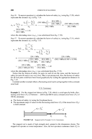
                  Example 2. For the stepped rod shown in Fig. 7.20, which is acted upon by both a fluc-
                  tuating axial force (F 1 ) of between − 200 lb and 800 lb and a constant axial force (F 2 ) of
                  500 lb, determine
                   a. The factor-of-safety (n) using the Goodman theory
                   b. The maximum range of values for the fluctuating axial force (F 1 ) if the mean force (F m )
                     is held constant
                                              3 "
                                          d  =   16            d  =  1 "
                                           1
                                                                2
                                                                   8
                                                       F 1           F 2
                              FIGURE 7.20  Stepped rod for Example 2 (U.S. Customary).
                    The stepped rod is made of high-strength steel, ground to the dimensions shown. The

                  stepped rod operates at room temperature. Also, the test specimen endurance limit (S ) is
                                                                                e
   311   312   313   314   315   316   317   318   319   320   321