
Page 319 - Marks Calculation for Machine Design
P. 319
P1: Shashi
15:4
January 4, 2005
Brown.cls
Brown˙C07
FATIGUE AND DYNAMIC DESIGN
Step 14. Multiply the factor-of-safety (n m ) found in step 13 times the alternating axial
force (F a ) to give a maximum alternating axial force (F a max ) as 301
F a max = n m F a = (1.88)(500 lb) = 940 lb
Step 15. Use the maximum alternating axial force (F a max ) found in step 14 to determine
the limiting values of the maximum axial force (F max ) and the minimum axial force (F min ).
F lim = F m + F max = (800 lb) + (940 lb) = 1,740 lb
max a
lim max
F = F m − F = (800 lb) − (940 lb) =−140 lb
min a
Step 16. Subtract the constant axial force (F 2 ) from the limiting values in step 15 to give
the limiting range of the fluctuating axial force (F 1 ) forcing the factor-of-safety to be 1.
F max = F lim − F 2 = (1,740 lb) − (500 lb) = 1,240 lb
1 max
lim
F 1 min = F min − F 2 = (−140 lb) − (500 lb) =−640 lb
This means the limiting range on the fluctuating force (F 1 ) is −640 lb to 1,240 lb.
SI/metric
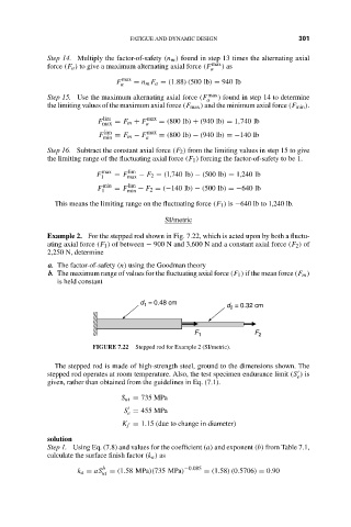
Example 2. For the stepped rod shown in Fig. 7.22, which is acted upon by both a fluctu-
ating axial force (F 1 ) of between − 900 N and 3,600 N and a constant axial force (F 2 ) of
2,250 N, determine
a. The factor-of-safety (n) using the Goodman theory
b. The maximum range of values for the fluctuating axial force (F 1 ) if the mean force (F m )
is held constant
d = 0.48 cm d = 0.32 cm
1
2
F 1 F 2
FIGURE 7.22 Stepped rod for Example 2 (SI/metric).
The stepped rod is made of high-strength steel, ground to the dimensions shown. The
stepped rod operates at room temperature. Also, the test specimen endurance limit (S ) is
e
given, rather than obtained from the guidelines in Eq. (7.1).
S ut = 735 MPa
S = 455 MPa
e
K f = 1.15 (due to change in diameter)
solution
Step 1. Using Eq. (7.8) and values for the coefficient (a) and exponent (b) from Table 7.1,
calculate the surface finish factor (k a ) as
b −0.085
k a = aS ut = (1.58 MPa)(735 MPa) = (1.58)(0.5706) = 0.90