Page 321 - Marks Calculation for Machine Design
P. 321

P1: Shashi
                          January 4, 2005
                 Brown˙C07
        Brown.cls
                           (s )
                         329.0 a  S e  15:4 FATIGUE AND DYNAMIC DESIGN            303
                                                         Scale: 17.5 MPa  × 17.5 MPa
                          280
                                                  Calculated stresses
                          210
                                                                  Goodman line
                          140      s m
                         124.3
                           70             s a
                                                                       S ut
                            0                                               (s )
                              0     140 198.9  280  420     560     700 770   m
                                                                      735
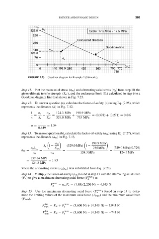
                        FIGURE 7.23  Goodman diagram for Example 2 (SI/metric).
                    Step 11. Plot the mean axial stress (σ m ) and alternating axial stress (σ a ) from step 10, the
                    given ultimate tensile strength (S ut ), and the endurance limit (S e ) calculated in step 6 in a
                    Goodman diagram like that shown in Fig. 7.23.
                    Step 12. To answer question (a), calculate the factor-of-safety (n) using Eq. (7.25), which
                    represents the distance (d) in Fig. 7.12.
                         1   σ a  σ m  124.3MPa  198.9MPa
                           =   +     =         +          = (0.378) + (0.271) = 0.649
                         n   S e  S ut  329.0MPa  735 MPa
                               1
                         n =      = 1.54
                             0.649
                    Step 13. To answer question (b), calculate the factor-of-safety (n m ) using Eq. (7.27), which
                    represents the distance (d m ) in Fig. 7.13.


                                      σ m                 198.9MPa
                                S e 1 −     (329.0MPa) 1 −
                         σ a | σ m    S ut                 735 MPa    (329.0MPa)(0.729)
                    n m =     =           =                         =
                          σ a       σ a             124.3MPa             124.3MPa
                         239.84 MPa
                       =           = 1.93
                         124.3MPa
                                             ) was substituted from Eq. (7.28).
                    where the alternating stress (σ a | σ m
                    Step 14. Multiply the factor-of-safety (n m ) found in step 13 with the alternating axial force
                    (F a ) to give a maximum alternating axial force (F a max ) as
                                    F max  = n m F a = (1.93)(2,250 N) = 4,343 N
                                     a
                    Step 15. Use the maximum alternating axial force (F a max ) found in step 14 to deter-
                    mine the limiting values of the maximum axial force (F max ) and the minimum axial force
                    (F min ).

                                lim
                               F max  = F m + F a max  = (3,600 N) + (4,343 N) = 7,943 N
                                 lim       max
                               F   = F m − F  = (3,600 N) − (4,343 N) =−743 N
                                min        a
   316   317   318   319   320   321   322   323   324   325   326