
Page 313 - Marks Calculation for Machine Design
P. 313
P1: Shashi
15:4
January 4, 2005
Brown.cls
Brown˙C07
FATIGUE AND DYNAMIC DESIGN
Step 16. To answer question (c), calculate the factor-of-safety (n a ) using Eq. (7.29), which
represents the distance (d a ) in Fig. 7.14. 295
σ a 12.3 kpsi
S ut 1 − (85 kpsi) 1 −
σ m | σ a S e 32.7 kpsi (85 kpsi)(0.624)
n a = = = =
σ m σ m 30.6 kpsi 30.6 kpsi
53.04 kpsi
= = 1.73
30.6 kpsi
) was substituted from Eq. (7.30).
where the alternating stress (σ m | σ a
Step 17. To answer question (d), calculate the factor-of-safety (n c ) using Eq. (7.31), which
represents the distance (d c ) in Fig. 7.15.
S e
S e σ a
+
σ m | c S ut σ m S e
n c = = =
σ m σ m S e σ a
σ m +
S ut σ m
32.7 kpsi 32.7 kpsi
= =
32.7 kpsi 12.3 kpsi (30.6 kpsi)(0.385 + 0.402)
(30.6 kpsi) +
85 kpsi 30.6 kpsi
32.7 kpsi 32.7 kpsi
= = = 1.36
(30.6 kpsi)(0.787) 24.08 kpsi
where the alternating stress (σ m | c ) was substituted from Eq. (7.32).
Notice that the factors-of-safety for parts (a) and (d) are the same, and the factors-of-safety
for parts (b) and (c) are very close. This is not unexpected. Also, the factors-of-safety for all
fourpartscouldhavebeenfoundgraphicallybyscalingtheappropriatedistancesinFig.7.17.
SI/Metric
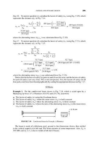
Example 1. For the cantilevered beam shown in Fig. 7.18, which is acted upon by a
fluctuating tip force (F) of between (10.8 N) and (25.2 N), determine
a. The factor-of-safety (n) using the Goodman theory
b. The factor-of-safety (n m ) where the mean stress (σ m ) is held constant
c. The factor-of-safety (n a ) where the alternating stress (σ a ) is held constant
d. The factor-of-safety (n c ) where the ratio of the alternating stress (σ a ) to the mean stress
(σ m ) is held constant
F 0.16 cm
1.25 cm
6 cm
FIGURE 7.18 Cantilevered beam for Example 1 (SI/metric).
The beam is made of cold-drawn steel, ground to the dimensions shown, then welded
to the vertical support at its left end. The beam operates at room temperature. Also, S ut is
595 MPa and K f is 1.2 (due to welds at left end of beam).