
Page 312 - Marks Calculation for Machine Design
P. 312
P1: Shashi
Brown˙C07
Brown.cls
294
Step 12. Calculate the mean bending stress (σ m ) and the alternating bending stress (σ a )
as January 4, 2005 15:4 STRENGTH OF MACHINES
M m c (10 in · lb)(0.03125 in)
σ m = = = 30.6 kpsi
I 1.02 × 10 −5 in 4
M a c (4in · lb)(0.03125 in)
σ a = = = 12.3 kpsi
I 1.02 × 10 −5 in 4
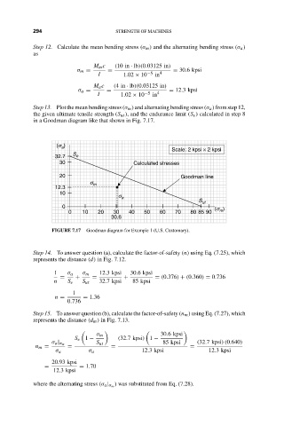
Step13. Plotthemeanbendingstress (σ m )andalternatingbendingstress(σ a )fromstep12,
the given ultimate tensile strength (S ut ), and the endurance limit (S e ) calculated in step 8
in a Goodman diagram like that shown in Fig. 7.17.
)
(s a
Scale: 2 kpsi × 2 kpsi
32.7 S e
30 Calculated stresses
20 Goodman line
s m
12.3
10
s a
S ut
0
(s m )
0 10 20 30 40 50 60 70 80 85 90
30.6
FIGURE 7.17 Goodman diagram for Example 1 (U.S. Customary).
Step 14. To answer question (a), calculate the factor-of-safety (n) using Eq. (7.25), which
represents the distance (d) in Fig. 7.12.
1 σ a σ m 12.3 kpsi 30.6 kpsi
= + = + = (0.376) + (0.360) = 0.736
n S e S ut 32.7 kpsi 85 kpsi
1
n = = 1.36
0.736
Step 15. To answer question (b), calculate the factor-of-safety (n m ) using Eq. (7.27), which
represents the distance (d m ) in Fig. 7.13.
σ m 30.6 kpsi
S e 1 − (32.7 kpsi) 1 −
σ a | σ m S ut 85 kpsi (32.7 kpsi)(0.640)
n m = = = =
σ a σ a 12.3 kpsi 12.3 kpsi
20.93 kpsi
= = 1.70
12.3 kpsi
) was substituted from Eq. (7.28).
where the alternating stress (σ a | σ m