
Page 309 - Marks Calculation for Machine Design
P. 309
P1: Shashi
January 4, 2005
Brown˙C07
Brown.cls
Alternating stress (s a ) S e 15:4 FATIGUE AND DYNAMIC DESIGN 291
Goodman line
Calculated stresses
Right triangle
s
- alternating stress constant
a
0 d a
0 s m s S
m s
a ut
Mean stress (s )
m
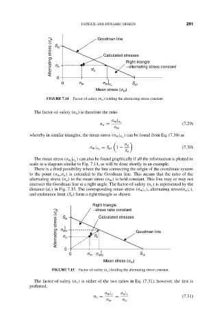
FIGURE 7.14 Factor-of-safety (n a ) holding the alternating stress constant.
The factor-of-safety (n a ) is therefore the ratio
σ m | σ a
n a = (7.29)
σ m
) can be found from Eq. (7.30) as
whereby in similar triangles, the mean stress (σ m | σ a
σ a
= S ut 1 − (7.30)
σ m | σ a
S e
) can also be found graphically if all the information is plotted to
The mean stress (σ m | σ a
scale in a diagram similar to Fig. 7.14, as will be done shortly in an example.
There is a third possibility where the line connecting the origin of the coordinate system
to the point (σ m ,σ a ) is extended to the Goodman line. This means that the ratio of the
alternating stress (σ a ) to the mean stress (σ m ) is held constant. This line may or may not
intersect the Goodman line at a right angle. The factor-of-safety (n c ) is represented by the
distance (d c ) in Fig. 7.15. The corresponding mean stress (σ m | c ), alternating stress(σ a | c ),
and endurance limit (S e ) form a right triangle as shown.
Right triangle
- stress ratio constant
Alternating stress (s a ) s e a d c Calculated stresses Goodman line
S
a c
s
0
0 s m s S ut
m c
Mean stress (s )
m
FIGURE 7.15 Factor-of-safety (n c ) holding the alternating stress constant.
The factor-of-safety (n c ) is either of the two ratios in Eq. (7.31); however, the first is
preferred.
σ m | c σ a | c
n c = = (7.31)
σ m σ a