
Page 308 - Marks Calculation for Machine Design
P. 308
P1: Shashi
January 4, 2005
Brown˙C07
Brown.cls
290
Alternating stress (s a ) S e 15:4 d STRENGTH OF MACHINES Goodman line
Calculated stresses
s a
0
0 s m S ut
Mean stress (s )
m
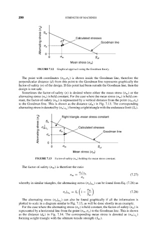
FIGURE 7.12 Graphical approach using the Goodman theory.
The point with coordinates (σ m ,σ a ) is shown inside the Goodman line, therefore the
perpendicular distance (d) from this point to the Goodman line represents graphically the
factor-of-safety (n) of the design. If this point had been outside the Goodman line, then the
design is not safe.
Sometimes the factor-of-safety (n) is desired where either the mean stress (σ m ) or the
alternating stress (σ a ) is held constant. For the case where the mean stress (σ m ) is held con-
stant, the factor-of-safety (n m ) is represented by a vertical distance from the point (σ m ,σ a )
to the Goodman line. This is shown as the distance (d m ) in Fig. 7.13. The corresponding
) forming aright triangle with the endurancelimit (S e ).
alternatingstress isdenotedby (σ a | σ m
Alternating stress (s a ) s S m e a d m Calculated stresses Goodman line
Right triangle-mean stress constant
a s
s
0
0 s m S ut
Mean stress (s )
m
FIGURE 7.13 Factor-of-safety (n m ) holding the mean stress constant.
The factor-of-safety (n m ) is therefore the ratio
σ a | σ m
n m = (7.27)
σ a
) can be found from Eq. (7.28) as
whereby in similar triangles, the alternating stress (σ a | σ m
σ m
= S e 1 − (7.28)
σ a | σ m
S ut
) can also be found graphically if all the information is
The alternating stress (σ a | σ m
plotted to scale in a diagram similar to Fig. 7.13, as will be done shortly in an example.
For the case where the alternating stress (σ a ) is held constant, the factor-of-safety (n a ) is
represented by a horizontal line from the point (σ m ,σ a ) to the Goodman line. This is shown
)
as the distance (d a ) in Fig. 7.14. The corresponding mean stress is denoted as (σ m | σ a
forming a right triangle with the ultimate tensile strength (S ut ).