
Page 333 - Marks Calculation for Machine Design
P. 333
P1: Shashi
January 4, 2005
Brown˙C07
Brown.cls
40
eff
(s )
m 15:4 FATIGUE AND DYNAMIC DESIGN 315
Scale: 2 kpsi × 2 kpsi
Calculated stresses
30 S e
28.8
23
20 s eff Goodman line
m
10 s a eff
S ut
0 (s )
eff
0 10 20 30 40 50 60 70 80 90 m
17 75
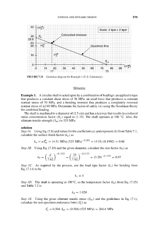
FIGURE 7.31 Goodman diagram for Example 1 (U.S. Customary).
SI/metric
Example 1. A circular shaft is acted upon by a combination of loadings: an applied torque
that produces a constant shear stress of 56 MPa, an axial force that produces a constant
normal stress of 70 MPa, and a bending moment that produces a completely reversed
normal stress of ±140 MPa. Determine the factor-of-safety (n) using the Goodman theory
for combined loading.
The shaft is machined to a diameter of (2.5 cm) and has a keyway that results in a reduced
◦
stress concentration factor (K f ) equal to (1.15). The shaft operates at 100 C. Also, the
ultimate tensile strength (S ut ) is 525 MPa.
solution
Step 1A. Using Eq. (7.8) and values for the coefficient (a) and exponent (b) from Table 7.1,
calculate the surface finish factor (k a ) as
b −0.265
k a = aS ut = (4.51 MPa)(525 MPa) = (4.51)(0.1902) = 0.86
Step 1B. Using Eq. (7.10) and the given diameter, calculate the size factor (k b ) as
−0.1133 −0.1133
d 25 −0.1133
k b = = = (3.28) = 0.87
7.62 7.62
Step 1C. As required by the process, use the load type factor (k c ) for bending from
Eq. (7.14) to be
k c = 1
◦
Step 1D. The shaft is operating at 100 C, so the temperature factor (k d ) from Eq. (7.15)
and Table 7.2 is
k d = 1.020
Step 1E. Using the given ultimate tensile stress (S ut ) and the guidelines in Eq. (7.1),
calculate the test specimen endurance limit (S ) as
e
S = 0.504 S ut = (0.504)(525 MPa) = 264.6MPa
e