
Page 132 - Master Handbook of Acoustics
P. 132
Adjustable filters can be shifted to any frequency within their design band. One type is the constant
bandwidth filter that offers the same bandwidth at any frequency. For example, a spectrum analyzer
may have a 5-Hz bandwidth, whether it is tuned to 100 Hz or 10 kHz, or any other frequency within
its operating band. Another adjustable filter offers a pass bandwidth that is a constant percentage of
the frequency to which it is tuned. The 1/3-octave filter is such a device. If it is tuned to 125 Hz, the
1/3-octave bandwidth is 112 to 141 Hz. If it is tuned to 8 kHz, the 1/3-octave bandwidth is 7,079 to
8,913 Hz. In either case, the bandwidth is about 23% of the frequency to which it is tuned.
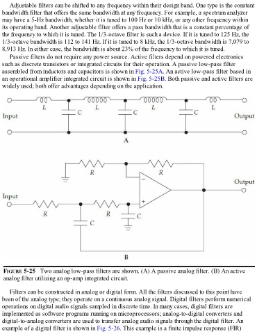
Passive filters do not require any power source. Active filters depend on powered electronics
such as discrete transistors or integrated circuits for their operation. A passive low-pass filter
assembled from inductors and capacitors is shown in Fig. 5-25A. An active low-pass filter based in
an operational amplifier integrated circuit is shown in Fig. 5-25B. Both passive and active filters are
widely used; both offer advantages depending on the application.
FIGURE 5-25 Two analog low-pass filters are shown. (A) A passive analog filter. (B) An active
analog filter utilizing an op-amp integrated circuit.
Filters can be constructed in analog or digital form. All the filters discussed to this point have
been of the analog type; they operate on a continuous analog signal. Digital filters perform numerical
operations on digital audio signals sampled in discrete time. In many cases, digital filters are
implemented as software programs running on microprocessors; analog-to-digital converters and
digital-to-analog converters are used to transfer analog audio signals through the digital filter. An
example of a digital filter is shown in Fig. 5-26. This example is a finite impulse response (FIR)