
Page 130 - Master Handbook of Acoustics
P. 130
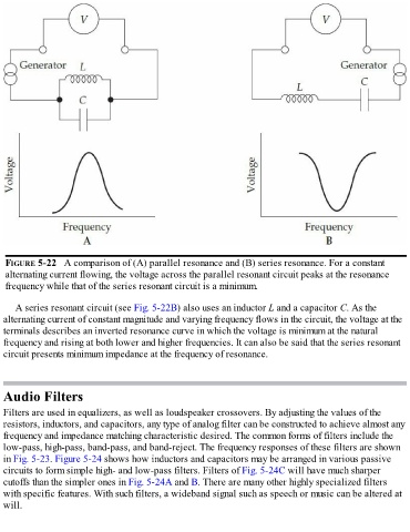
FIGURE 5-22   A comparison of (A) parallel resonance and (B) series resonance. For a constant
   alternating current flowing, the voltage across the parallel resonant circuit peaks at the resonance
   frequency while that of the series resonant circuit is a minimum.


      A series resonant circuit (see Fig. 5-22B) also uses an inductor L and a capacitor C. As the

  alternating current of constant magnitude and varying frequency flows in the circuit, the voltage at the
  terminals describes an inverted resonance curve in which the voltage is minimum at the natural
  frequency and rising at both lower and higher frequencies. It can also be said that the series resonant
  circuit presents minimum impedance at the frequency of resonance.


  Audio Filters

  Filters are used in equalizers, as well as loudspeaker crossovers. By adjusting the values of the
  resistors, inductors, and capacitors, any type of analog filter can be constructed to achieve almost any
  frequency and impedance matching characteristic desired. The common forms of filters include the
  low-pass, high-pass, band-pass, and band-reject. The frequency responses of these filters are shown

  in Fig. 5-23. Figure 5-24 shows how inductors and capacitors may be arranged in various passive
  circuits to form simple high- and low-pass filters. Filters of Fig. 5-24C will have much sharper
  cutoffs than the simpler ones in Fig. 5-24A and B. There are many other highly specialized filters
  with specific features. With such filters, a wideband signal such as speech or music can be altered at
  will.