
Page 129 - Master Handbook of Acoustics
P. 129
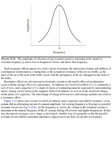
FIGURE 5-21   The amplitude of vibration of any resonant system is maximum at the natural or
   resonant frequency f  and is less at frequencies below and above that frequency.
                          0


      Such resonance effects appear in a wide variety of systems: the interaction of mass and stiffness of
  a mechanical system such as a tuning fork, or the acoustical resonance of the air in a bottle, as the
  mass of the air in the neck of the bottle reacts with the springiness of the air entrapped in the body of
  the bottle.

      Resonance effects are also present in electronic circuits as the inertia effect of an inductance
  reacts with the storage effect of a capacitance. An inductor (its electrical symbol is L) is commonly a
  coil of wire, and a capacitor (C) is made of sheets of conducting material separated by nonconducting
  sheets. Energy can be stored in the magnetic field of an inductor as well as in the electrical charges
  on the plates of a capacitor. The interchange of energy between two such storage systems can result in
  a resonance effect.

      Figure 5-22 shows two circuits in which an inductor and a capacitor can exhibit resonance. Let us
  assume that an alternating current of constant amplitude, but varying frequency is flowing in a parallel
  resonant circuit (see Fig. 5-22A). As the frequency is varied, the voltage at the terminals reaches a
  maximum at the natural frequency of the LC system, falling off at lower and higher frequencies. In this
  way the typical resonance curve shape is developed. Another way of saying this is that the parallel
  resonant circuit exhibits maximum impedance (opposition to the flow of current) at resonance.