
Page 230 - Mastering SolidWorks
P. 230
|
SketchinG in 3D 201
the FeatureManager Filter at the top of the FeatureManager. The Advanced Search function in
assemblies can also search metadata sources. SolidWorks Explorer is a good first-level data
management solution that can search, display, and edit metadata and previews. Windows
Explorer can also search properties and tags.
Creating Construction Geometry
In SolidWorks, the only construction geometry that can be created directly is the construction
line. All other sketch entities can be converted to construction geometry by selecting the
Construction Geometry option within the sketch entity’s PropertyManager or by using
the Construction Geometry toggle toolbar button.
SolidWorks terminology is inconsistent, because it sometimes refers to construction lines as
centerlines. The two are really the same thing. Centerlines are used for revolved sketches and
mirroring, but there is no difference between a centerline and a construction line in SolidWorks.
Construction geometry is useful for many different types of situations. I use it frequently for
reference sketch data. You can make sketch relations to construction geometry, to create symme-
try, and you can use it for layout sketches or many other purposes.
Sketching in 3D
The 3D sketch is an important tool for creating weldments (and many other features) in
SolidWorks. 3D sketches can be challenging, but they are certainly manageable if you know what
to expect from them.
Earlier chapters discussed the tools that are available for 2D sketches; next, I cover techniques
for 3D sketching.
Navigating in Space
To start a 3D sketch, activate the 3D Sketch icon on the flyout under the 2D sketch icon; or, in the
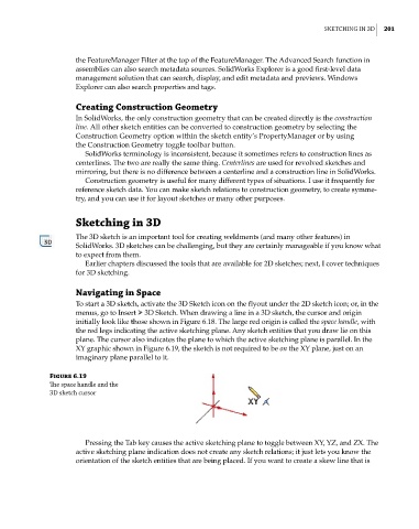
menus, go to Insert ➢ 3D Sketch. When drawing a line in a 3D sketch, the cursor and origin
initially look like those shown in Figure 6.18. The large red origin is called the space handle, with
the red legs indicating the active sketching plane. Any sketch entities that you draw lie on this
plane. The cursor also indicates the plane to which the active sketching plane is parallel. In the
XY graphic shown in Figure 6.19, the sketch is not required to be on the XY plane, just on an
imaginary plane parallel to it.
Figure 6.19
The space handle and the
3D sketch cursor
Pressing the Tab key causes the active sketching plane to toggle between XY, YZ, and ZX. The
active sketching plane indication does not create any sketch relations; it just lets you know the
orientation of the sketch entities that are being placed. If you want to create a skew line that is