
Page 231 - Mastering SolidWorks
P. 231
|
202 CHAPTER 6 GettinG More froM Your SketcheS
not parallel to any standard plane, you can do this by sketching to available endpoints, vertices,
origins, and so on. If there are no entities to snap to, you will need to accept the planar place-
ment, turn off the sketch tool, rotate the view, and move one end of the sketch entity.
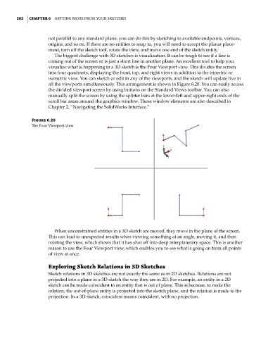
The biggest challenge with 3D sketches is visualization. It can be tough to see if a line is
coming out of the screen or is just a short line in another plane. An excellent tool to help you
visualize what is happening in a 3D sketch is the Four Viewport view. This divides the screen
into four quadrants, displaying the front, top, and right views in addition to the trimetric or
isometric view. You can sketch or edit in any of the viewports, and the sketch will update live in
all the viewports simultaneously. This arrangement is shown in Figure 6.20. You can easily access
the divided viewport screen by using buttons on the Standard Views toolbar. You can also
manually split the screen by using the splitter bars at the lower-left and upper-right ends of the
scroll bar areas around the graphics window. These window elements are also described in
Chapter 2, “Navigating the SolidWorks Interface.”
Figure 6.20
The four Viewport view
When unconstrained entities in a 3D sketch are moved, they move in the plane of the screen.
This can lead to unexpected results when viewing something at an angle, moving it, and then
rotating the view, which shows that it has shot off into deep interplanetary space. This is another
reason to use the Four Viewport view, which enables you to see what is going on from all points
of view at once.
Exploring Sketch Relations in 3D Sketches
Sketch relations in 3D sketches are not exactly the same as in 2D sketches. Relations are not
projected into a plane in a 3D sketch the way they are in 2D. For example, an entity in a 2D
sketch can be made coincident to an entity that is out of plane. This is because, to make the
relation, the out-of-plane entity is projected into the sketch plane, and the relation is made to the
projection. In a 3D sketch, coincident means coincident, with no projection.