
Page 281 - Mastering SolidWorks
P. 281
|
using chaMFers 253
4. Select the setback vertices. In the Setback Parameters panel of the PropertyManager, with
the second box from the top highlighted, select the vertices. Although this box looks as if it
is only big enough for a single selection, it can accept multiple selections.
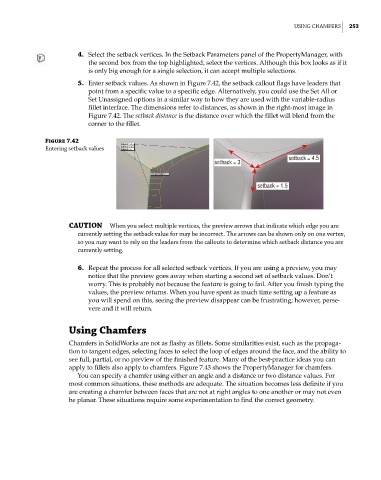
5. Enter setback values. As shown in Figure 7.42, the setback callout flags have leaders that
point from a specific value to a specific edge. Alternatively, you could use the Set All or
Set Unassigned options in a similar way to how they are used with the variable-radius
fillet interface. The dimensions refer to distances, as shown in the right-most image in
Figure 7.42. The setback distance is the distance over which the fillet will blend from the
corner to the fillet.
Figure 7.42
entering setback values
setback = 4.5
setback = 3
setback = 1.5
CAUTION when you select multiple vertices, the preview arrows that indicate which edge you are
currently setting the setback value for may be incorrect. the arrows can be shown only on one vertex,
so you may want to rely on the leaders from the callouts to determine which setback distance you are
currently setting.
6. Repeat the process for all selected setback vertices. If you are using a preview, you may
notice that the preview goes away when starting a second set of setback values. Don’t
worry. This is probably not because the feature is going to fail. After you finish typing the
values, the preview returns. When you have spent as much time setting up a feature as
you will spend on this, seeing the preview disappear can be frustrating; however, perse-
vere and it will return.
Using Chamfers
Chamfers in SolidWorks are not as flashy as fillets. Some similarities exist, such as the propaga-
tion to tangent edges, selecting faces to select the loop of edges around the face, and the ability to
see full, partial, or no preview of the finished feature. Many of the best-practice ideas you can
apply to fillets also apply to chamfers. Figure 7.43 shows the PropertyManager for chamfers.
You can specify a chamfer using either an angle and a distance or two distance values. For
most common situations, these methods are adequate. The situation becomes less definite if you
are creating a chamfer between faces that are not at right angles to one another or may not even
be planar. These situations require some experimentation to find the correct geometry.