
Page 285 - Mastering SolidWorks
P. 285
|
tutorial: BracKet casting 257
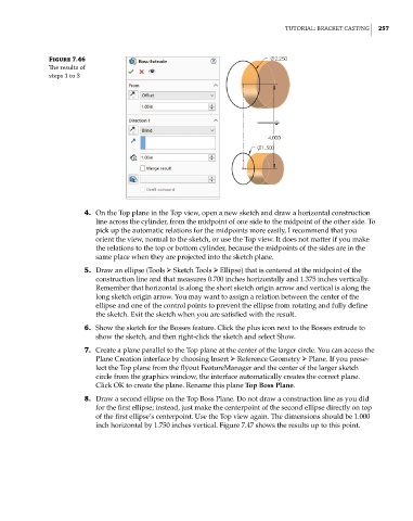
Figure 7.46
The results of
steps 1 to 3
4. On the Top plane in the Top view, open a new sketch and draw a horizontal construction
line across the cylinder, from the midpoint of one side to the midpoint of the other side. To
pick up the automatic relations for the midpoints more easily, I recommend that you
orient the view, normal to the sketch, or use the Top view. It does not matter if you make
the relations to the top or bottom cylinder, because the midpoints of the sides are in the
same place when they are projected into the sketch plane.
5. Draw an ellipse (Tools ➢ Sketch Tools ➢ Ellipse) that is centered at the midpoint of the
construction line and that measures 0.700 inches horizontally and 1.375 inches vertically.
Remember that horizontal is along the short sketch origin arrow and vertical is along the
long sketch origin arrow. You may want to assign a relation between the center of the
ellipse and one of the control points to prevent the ellipse from rotating and fully define
the sketch. Exit the sketch when you are satisfied with the result.
6. Show the sketch for the Bosses feature. Click the plus icon next to the Bosses extrude to
show the sketch, and then right-click the sketch and select Show.
7. Create a plane parallel to the Top plane at the center of the larger circle. You can access the
Plane Creation interface by choosing Insert ➢ Reference Geometry ➢ Plane. If you prese-
lect the Top plane from the flyout FeatureManager and the center of the larger sketch
circle from the graphics window, the interface automatically creates the correct plane.
Click OK to create the plane. Rename this plane Top Boss Plane.
8. Draw a second ellipse on the Top Boss Plane. Do not draw a construction line as you did
for the first ellipse; instead, just make the centerpoint of the second ellipse directly on top
of the first ellipse’s centerpoint. Use the Top view again. The dimensions should be 1.000
inch horizontal by 1.750 inches vertical. Figure 7.47 shows the results up to this point.