
Page 286 - Mastering SolidWorks
P. 286
|
258 CHAPTER 7 Modeling with PriMary Features
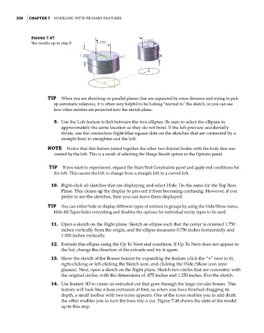
Figure 7.47
The results up to step 8
TIP when you are sketching on parallel planes that are separated by some distance and trying to pick
up automatic relations, it is often very helpful to be looking “normal to” the sketch, so you can see
how other entities are projected into the sketch plane.
9. Use the Loft feature to loft between the two ellipses. Be sure to select the ellipses in
approximately the same location so they do not twist. If the loft preview accidentally
twists, use the connectors (light-blue square dots on the sketches that are connected by a
straight line) to straighten out the loft.
NOTE notice that this feature joined together the other two disjoint bodies with the body that was
created by the loft. this is a result of selecting the Merge result option in the options panel.
TIP if you want to experiment, expand the start/end constraints panel and apply end conditions for
the loft. this causes the loft to change from a straight loft to a curved loft.
10. Right-click all sketches that are displaying and select Hide. Do the same for the Top Boss
Plane. This cleans up the display to prevent it from becoming confusing. However, if you
prefer to see the sketches, then you can leave them displayed.
TIP you can either hide or display different types of entities in groups by using the hide/show menu.
hide all types hides everything and disables the options for individual entity types to be used.
11. Open a sketch on the Right plane. Sketch an ellipse such that the center is oriented 1.750
inches vertically from the origin, and the ellipse measures 0.750 inches horizontally and
1.500 inches vertically.
12. Extrude this ellipse using the Up To Next end condition. If Up To Next does not appear in
the list, change the direction of the extrude and try it again.
13. Show the sketch of the Bosses feature by expanding the feature (click the “+” next to it),
right-clicking or left-clicking the Sketch icon, and clicking the Hide/Show icon (eye-
glasses). Next, open a sketch on the Right plane. Sketch two circles that are concentric with
the original circles, with the dimensions of .875 inches and 1.250 inches. Exit the sketch.
14. Use Instant 3D to create an extruded cut that goes through the large circular bosses. This
feature will look like a boss extrusion at first, so when you have finished dragging its
depth, a small toolbar with two icons appears. One of the icons enables you to add draft;
the other enables you to turn the boss into a cut. Figure 7.48 shows the state of the model
up to this step.