
Page 146 - Materials Science and Engineering An Introduction
P. 146
118 • Chapter 4 / Imperfections in Solids
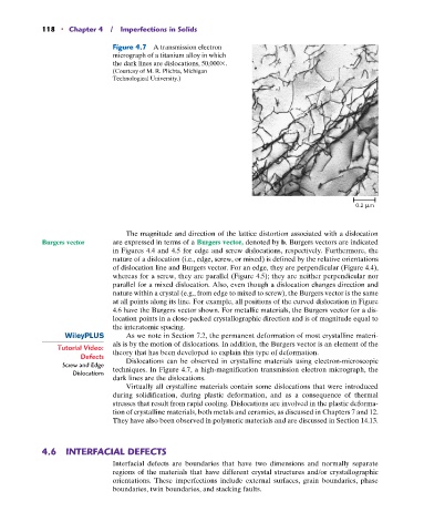
Figure 4.7 A transmission electron
micrograph of a titanium alloy in which
the dark lines are dislocations, 50,000 .
(Courtesy of M. R. Plichta, Michigan
Technological University.)
The magnitude and direction of the lattice distortion associated with a dislocation
Burgers vector are expressed in terms of a Burgers vector, denoted by b. Burgers vectors are indicated
in Figures 4.4 and 4.5 for edge and screw dislocations, respectively. Furthermore, the
nature of a dislocation (i.e., edge, screw, or mixed) is defined by the relative orientations
of dislocation line and Burgers vector. For an edge, they are perpendicular (Figure 4.4),
whereas for a screw, they are parallel (Figure 4.5); they are neither perpendicular nor
parallel for a mixed dislocation. Also, even though a dislocation changes direction and
nature within a crystal (e.g., from edge to mixed to screw), the Burgers vector is the same
at all points along its line. For example, all positions of the curved dislocation in Figure
4.6 have the Burgers vector shown. For metallic materials, the Burgers vector for a dis-
location points in a close-packed crystallographic direction and is of magnitude equal to
the interatomic spacing.
As we note in Section 7.2, the permanent deformation of most crystalline materi-
als is by the motion of dislocations. In addition, the Burgers vector is an element of the
Tutorial Video: theory that has been developed to explain this type of deformation.
Defects Dislocations can be observed in crystalline materials using electron-microscopic
Screw and Edge techniques. In Figure 4.7, a high-magnification transmission electron micrograph, the
Dislocations
dark lines are the dislocations.
Virtually all crystalline materials contain some dislocations that were introduced
during solidification, during plastic deformation, and as a consequence of thermal
stresses that result from rapid cooling. Dislocations are involved in the plastic deforma-
tion of crystalline materials, both metals and ceramics, as discussed in Chapters 7 and 12.
They have also been observed in polymeric materials and are discussed in Section 14.13.
4.6 INTERFACIAL DEFECTS
Interfacial defects are boundaries that have two dimensions and normally separate
regions of the materials that have different crystal structures and/or crystallographic
orientations. These imperfections include external surfaces, grain boundaries, phase
boundaries, twin boundaries, and stacking faults.