
Page 227 - Materials Science and Engineering An Introduction
P. 227
6.12 Design/Safety Factors • 199
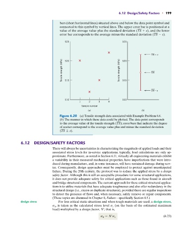
bars (short horizontal lines) situated above and below the data point symbol and
connected to this symbol by vertical lines. The upper error bar is positioned at a
value of the average value plus the standard deviation (TS + s), and the lower
error bar corresponds to the average minus the standard deviation (TS - s).
525 525
TS + s
Tensile strength (MPa) 515 Tensile strength (MPa) 515
520
520
TS
TS – s
510 510
1 2 3 4
Sample number
(a) (b)
Figure 6.20 (a) Tensile strength data associated with Example Problem 6.6.
(b) The manner in which these data could be plotted. The data point corresponds
to the average value of the tensile strength (TS); error bars that indicate the degree
of scatter correspond to the average value plus and minus the standard deviation
(TS { s).
6.12 DESIGN/SAFETY FACTORS
There will always be uncertainties in characterizing the magnitude of applied loads and their
associated stress levels for in-service applications; typically, load calculations are only ap-
proximate. Furthermore, as noted in Section 6.11, virtually all engineering materials exhibit
a variability in their measured mechanical properties, have imperfections that were intro-
duced during manufacture, and, in some instances, will have sustained damage during serv-
ice. Consequently, design approaches must be employed to protect against unanticipated
failure. During the 20th century, the protocol was to reduce the applied stress by a design
safety factor. Although this is still an acceptable procedure for some structural applications,
it does not provide adequate safety for critical applications such as those found in aircraft
and bridge structural components. The current approach for these critical structural applica-
tions is to utilize materials that have adequate toughnesses and also offer redundancy in the
structural design (i.e., excess or duplicate structures), provided there are regular inspections
to detect the presence of flaws and, when necessary, safely remove or repair components.
(These topics are discussed in Chapter 8, Failure—specifically Section 8.5.)
design stress For less critical static situations and when tough materials are used, a design stress,
(on the basis of the estimated maximum
s d , is taken as the calculated stress level s c
load) multiplied by a design factor, N¿; that is,
s d = N s c (6.23)